


GENERATOR START-UP PROCEDURE
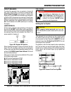
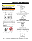
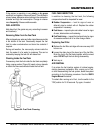
1. Place the circuit breakers (Figure
) in the OFF position prior to starting the engine.
Figure 36. Main, Aux. and GFCI
Circuit Breakers (OFF)
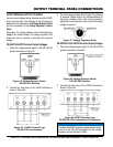
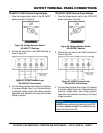
2. Connect the load to the receptacles or the output
terminal lugs as shown in Figure 10. These load
connection points can be found on the output terminal
panel and the output terminal panel’s hard wire hookup
panel.
3. Tighten terminal nuts securely to prevent load wires
from slipping out.
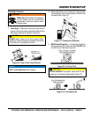
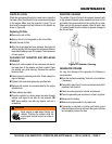
4. Close all engine enclosure doors (Figure 37).
Figure 37. Engine Enclosure Doors
CAUTION
The engine’s exhaust contains harmful emissions.
Direct exhaust away from nearby personnel.
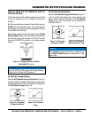
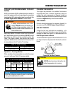
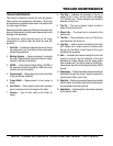
WARNING
manually start the engine with the main, GFCI
or auxiliary circuit breakers in the ON (closed) position.
INCORRECT
CORRECT
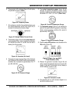
STARTING
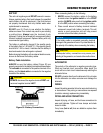
1. Place the voltage selector switch in the desired
voltage position (Figure 38)..
Figure 38. Voltage Selector Switch
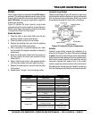
2. Preheat the engine glow plugs by turning the ignition
key (Figure 39) to the “OPERATION” position..
Figure 39. ignition Switch
3. When the preheat lamp goes OFF (Figure 40), turn
the ignition key to the “start” position. Once the engine
starts, release the ignition key and allow it to return to
the “operation” position (Figure 39).
Figure 40. Pre-Heat Lamp
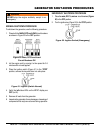
4. Once the engine starts, let the engine run for 1-2
minutes. Listen for any abnormal noises. If any
abnormalities exist, shut down the engine and correct
the problem.
5. The generator’s frequency meter (Figure 41) should be
displaying the 50 cycle output frequency in
Figure 41. Frequency Meter