


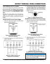
OUTPUT TERMINAL PANEL CONNECTIONS
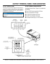
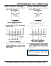
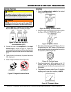
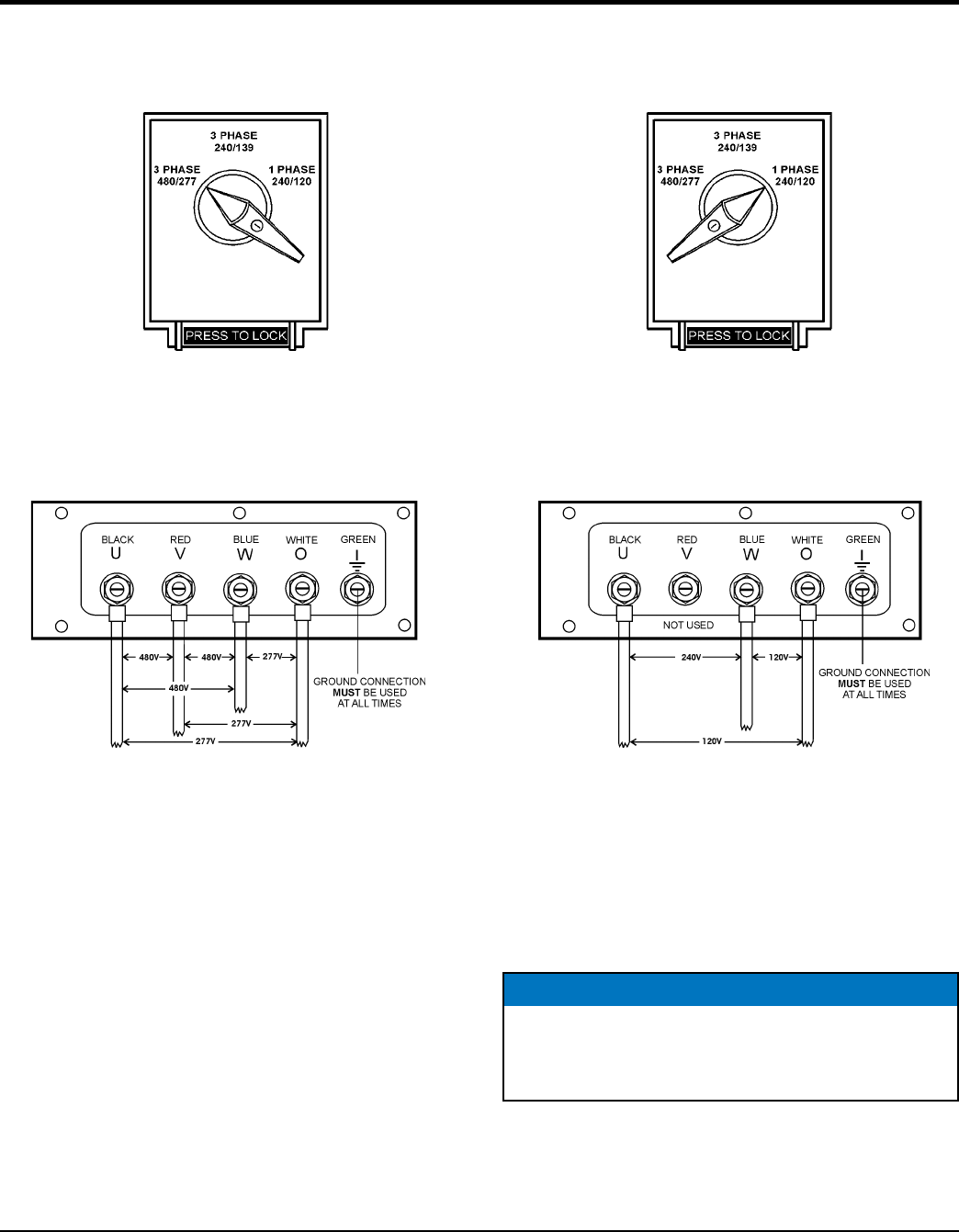
1. Place the voltage selector switch in the 3Ø 480/277
position as shown in Figure 24.
Figure 24. Voltage Selector Switch
3Ø-480/277V Position
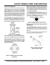
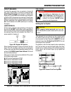
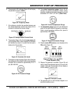
2. Connect the load wires to the UVWO terminals as
shown in Figure 25.
Figure 25. UVWO Terminal Lugs
3Ø-440/254V Connections
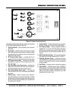
3. Turn the voltage regulator knob (Figure 21) clockwise
to increase voltage output, turn counterclockwise
to decrease voltage output. Use voltage regulator
adjustment knob whenever fine tuning of the output
voltage is required.
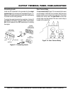
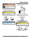
1. Place the voltage selector switch in the 1Ø 240/120
position as shown in Figure 26.
Figure 26. Voltage Selector Switch
1Ø-240/120V Position
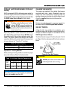
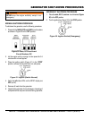
2. Connect the load wires to the UVWO terminals as
shown in Figure 27.
Figure 27. UVWO Terminal Lugs
1Ø-200/100V Connections
3. Turn the voltage regulator knob (Figure 21) clockwise
to increase voltage output, turn counterclockwise to
decrease voltage output. Use voltage regulator
adjustment knob whenever fine tuning of the output
voltage is required.
NOTICE
make sure that the connections to the UVWO
terminals are secure and tight. The possibility of arcing
exists, that could cause a fire.