DCA-25SSIU2 (50 HZ)— OPERATION AND PARTS MANUAL — REV. #0 (03/11/05) — PAGE 29
1
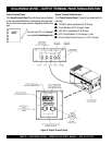
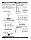
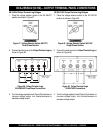
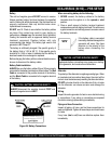
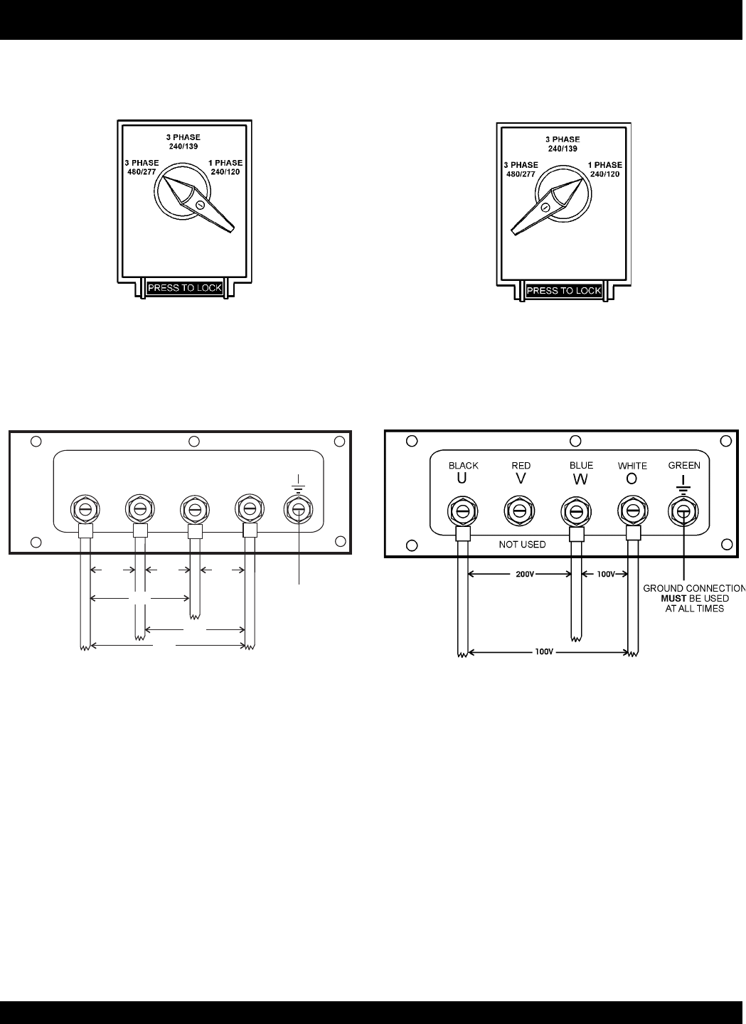
Figure 28. Output Terminal Lugs
3Ø-440/254V Three Phase Connections
2. Connect the load wires to the
Output Terminal Lugs
as
shown in Figure 28.
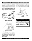
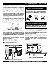
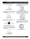
Figure 30. Output Terminal Lugs
1Ø-200/100V Connections
DCA-25SSIU2 (50 HZ)— OUTPUT TERMINAL PANEL CONNECTIONS
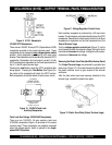
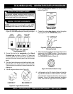
Figure 27. Voltage Selector Switch 480/277V
Three-Phase Position
3Ø 440/254 Output Terminal Lug Voltages
1. Place the voltage selector switch in the 3Ø 480/277
position as shown in Figure 27.
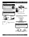
3. Turn the voltage regulator knob (Figure 24) clockwise to
increase voltage output, turn counterclockwise to
decrease voltage output.
1Ø 200V/100V Output Terminal Lug Voltages
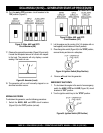
1. Place the voltage selector switch in the 1Ø 240/120
position as shown in Figure 29.
2. Connect the load wires to the
Output Terminal Lugs
as
shown in (Figure 30).
Figure 29. Voltage Selector Switch 240/120V
Single-Phase Position
3. Turn the voltage regulator knob (Figure 24) clockwise to
increase voltage output, turn counterclockwise to
decrease voltage output.
O
U
V
W
440V
BLACK RED
BLUE
440V
254V
440V
254V
WHITE
GREEN
254V
GROUND CONNECTION
BE USED
ATALLTIMES
MUST


