


DCA-15SPX3 GENERATOR — PARTS & OPERATION MANUAL — REV. #2 (09/03/01) — PAGE 25
DCA-15SPX3 — CONTROL PANEL
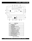
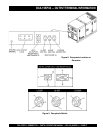
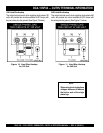
The definitions below describe the controls and functions of
the DCA-15SPX3 "
Control Panel Control Panel
Control Panel Control Panel
Control Panel
"(Figure 6).
1. Frequency Meter – Indicates the output frequency in
hertz (Hz). Normally 60 Hz
±
1 Hz.
2. AC Ammeter – Indicates the amount of current the
load is drawing from the generator.
3. AC Voltmeter – Indicates the single phase output
voltage present at the U & V terminals.
4. Engine Warning Indicator- This engine warning
indicator will notify possible damage before it occurs:
A. Oil Pressure - the light will go on during initial
start, but will go out once the engine is warm. If the
oil pressure light comes on during operation, this may
indicate critical low oil level.
B. Charge Light - This light indicates the battery is
not charging.
C. Water Temperature Light - This light indicates the
coolant temperature is abnormally high.
D. Engine Protection - This will shut down the engine
if there is an abnormal event that may have occurred.
This prevents damage to the engine.
5. Hour Meter – Indicates the amount of hours the
generator has been in operational use.
6. GFCI Circuit Breaker – This single-pole, 20 amp
breaker is provided to protect the 120 VAC GFCI
receptacle from overload.
7. Starter Switch - This is to turn on and off the engine
with a key.
8. CS6369 Receptacle - This locking type receptacle
provides 240/120VAC single output voltage, for
equipment not exceeding 50 amps.
9. 240 VAC Receptacle – Provides 240 VAC single phase
output voltage, normally used for small power tools
that do not exceed 20 amps.
10. 120 VAC Receptacle – Provides 120 VAC single phase
output voltage, normally used for small power tools
that do not exceed 20 amps.
11. 120VAC Receptacle (GFCI)- Provides 120 VAC single
phase output voltage, normally used for small power
tools that do not exceed 20 amps.
12. Engine Speed Control Lever - This lever controls
the speed of the engine speed from idle to high for
maximum rpm.
13. Ground Terminal – If required this ground terminal is
to be used in conjunction with the GFCI receptacle
only.
14. AC Output Terminals – These three output terminals
(UNV), provide the single phase output voltage to the
load source. NEVER connect a load to these output
terminals when the main circuit breaker is "ON" and
the engine is running.
15. Voltage Adjust Control Knob – Used to adjust the
generator's single phase output voltage at the UNV
output terminals. This control knob is to be used in
conjunction with the AC voltmeter.
16. Main Circuit Breaker – This three-pole, 65 amp main
breaker is provided to protect the single phase UNV
voltage output from overload.