


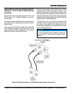
GENERATOR SHUT-DOWN PROCEDURES
To shutdown the generator, use the following procedure:
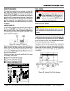
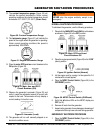
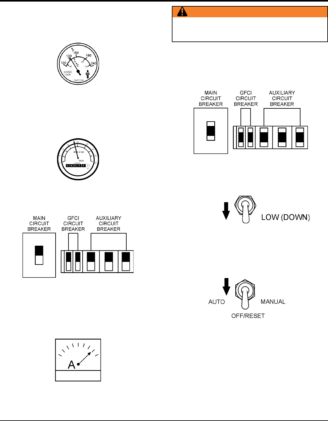
1. Place both the circuit breakers
as shown in Figure 54 to the OFF position..
Figure 54. Main, GFCI and Load
Circuit Breakers Off
2. Place the engine speed switch (Figure 55) in the “”
(down) position..
Figure 55. Ignition Switch (Normal)
3. Let the engine cool by running it at low speed for 3-5
minutes with no load applied.
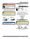
4. Place the (Figure 56) to the
position.
Figure 56. MPEC Control Switch (Off/Reset)
5. Verify that all status LEDs on the MPEC display are
OFF (not lit).
6. Remove all loads from the generator.
7. Inspect entire generator for any damage or loosening of
components that may have occurred during operation.
1. Place the (Figure 56) in the
position.
WARNING
stop the engine suddenly except in an
emergency.
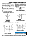
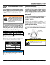
12. The coolant temperature gauge (Figure 50) will
indicate the coolant temperature. Under normal
operating conditions the coolant temperature should
be between 167°~203°F (75°~95°C) (Green Zone).
Figure 50. Coolant Temperature Gauge
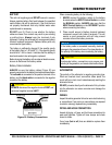
13. The tachometer gauge (Figure 51) will indicate the
speed of the engine when the generator is operating.
Under normal operating conditions this speed is
approximately 1800 RPM’s.
Figure 51. Engine Tachometer Gauge
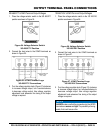
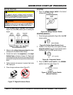
14. Place the circuit breakers in the
ON position (Figure 52).
Figure 52. Main, Aux. and GFCI
Circuit Breakers (ON)
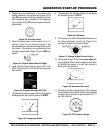
15. Observe the generator’s ammeter (Figure 53) and
verify it reads the anticipated amount of current with
respect to the load. The ammeter will only display a
current reading if a load is in use.
Figure 53. Ammeter (Load)
16. The generator will run until manually stopped or an
abnormal condition occurs.