


GENERATOR OUTPUTS
A wide range of voltages are available to supply voltage for
many different applications. Voltages are selected by using
the voltage selector switch (Figure 13). To obtain some of
the voltages as listed in Table 7 (see below) will require a
fine adjustment using the voltage regulator (VR) control
knob located on the control panel.
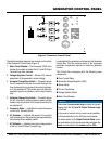
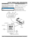
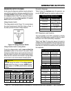
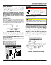
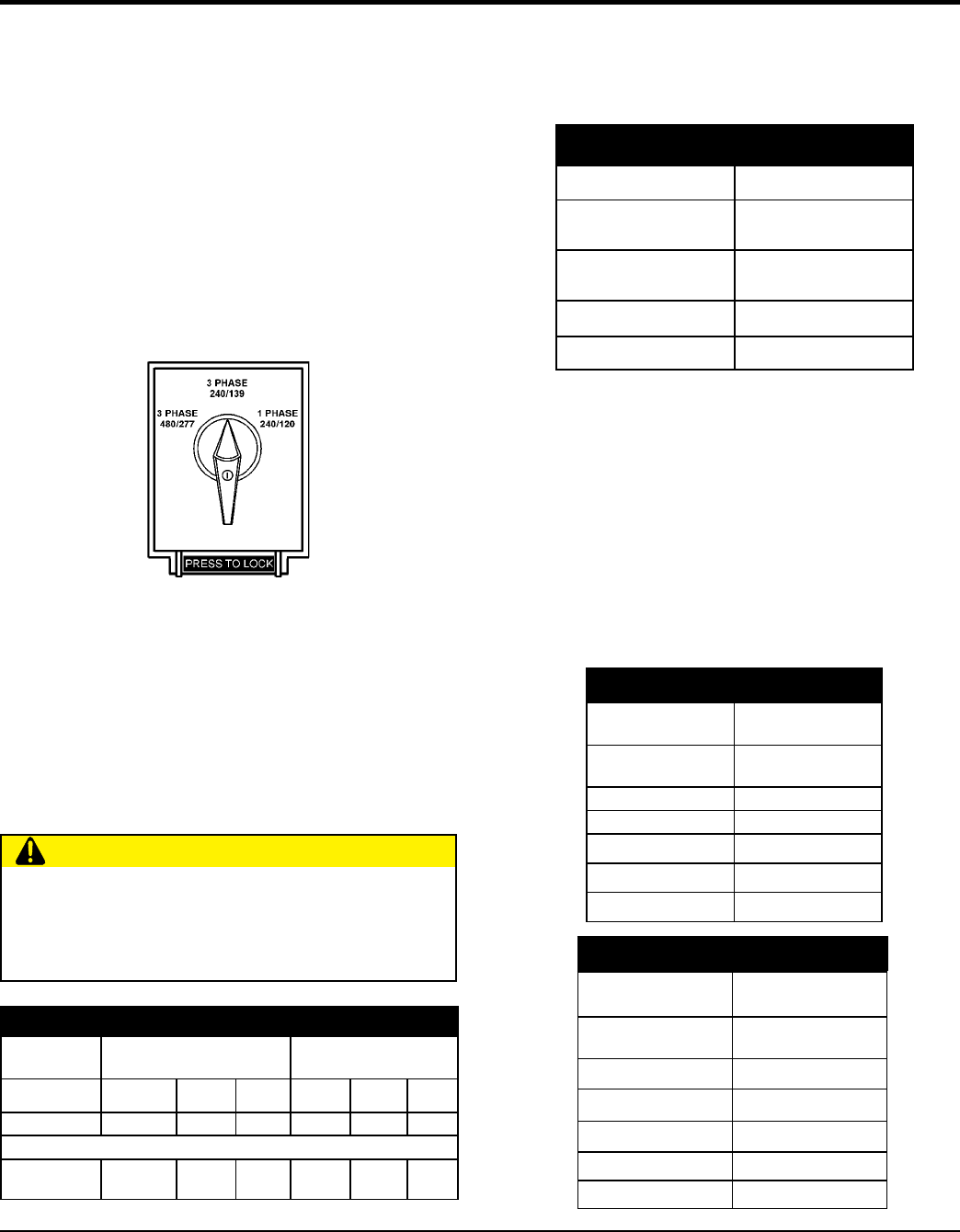
Voltage Selector Switch
The voltage selector switch (Figure 13) is located above
the output terminal panel’s Hard Wire Hook-up Panel. It
has been provided for ease of voltage selection.
Figure 13. Voltage Selector Switch
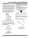
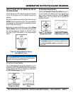
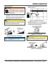
Voltage Selector Switch Locking Button
To lock the voltage selector switch, press and hold the
red button located at the bottom of the switch. While
holding the red button down, insert a pad lock into the hole
next to the button to retain it in the inward locked position.
When the lock is removed, the red button is spring loaded
and will return to its normal outward unlocked position.
CAUTION
change the position of the voltage selector
switch while the engine is running. place
circuit breaker in the OFF position before selecting
voltage
3Ø
208V 220V 240V 416V 440V 480V
1Ø 120V 127V 139V 240V 254V 277V
1Ø
120V
Line-Neutral
N/A N/A
240V
Line-Line
N/A N/A
Generator Amperage
Table 8 shows the maximum amps the generator can
provide. DO NOT exceed the maximum amps as listed..
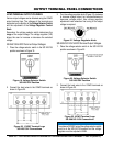
GFCI Receptacle Load Capability
The load capability of the GFCI receptacles is directly
related to the voltage being supplied at either the output
terminals or the 2 twist lock auxiliary receptacles.
Table 9 and Table 10 show what amount of current is
available at the GFCI receptacles when the output terminals
and twist lock receptacles are in use. Be careful that your
load does not to exceed the available current capability at
the receptacles.
1Ø 120 Volt
277.8 amps (4 wire)
301A x 2 (Zigzag)
1Ø 240 Volt
138.9 amps (4 wire)
301A (Zigzag)
3Ø 240 Volt 301 amps
3Ø 480 Volt 150 amps
KW in Use
1Ø 240/120V
GFCI Duplex
5-20R 120V
72.0 0 amps/receptacle
70.8 5 amps/receptacle
69.6 10 amps/receptacle
68.4 15 amps/receptacle
67.2 20 amps/receptacle
3Ø
3Ø 240/480V
GFCI Duplex
5-20R 120V
125
0 amps/receptacle
121
5 amps/receptacle
117
10 amps/receptacle
113
15 amps/receptacle
108
20 amps/receptacle