


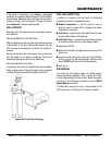

GENERATOR START-UP PROCEDURE
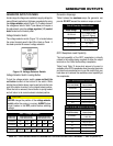
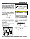
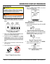
1. Place the circuit breakers
(Figure 36) in the OFF position prior to starting the
engine.
Figure 36. Main, Aux. and GFCI
Circuit Breakers (OFF)
2. Make sure the has been
configured for the desired output voltage.
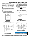
3. Connect the load to the receptacles or the output
terminal lugs as shown in Figure 10. These load
connection points can be found on the output terminal
panel and the output terminal panel’s hard wire hookup
panel.
4. Tighten terminal nuts securely to prevent load wires
from slipping out.
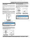
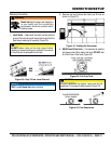
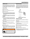
5. Close all engine enclosure doors (Figure 37).
Figure 37. Engine Enclosure Doors
CAUTION
The engine’s exhaust contains harmful emissions.
Direct exhaust away from nearby personnel.
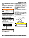
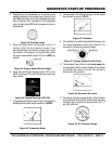
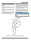
WARNING
manually start the engine with the main, GFCI or
auxiliary circuit breakers in the ON (closed) position.
INCORRECT
CORRECT
STARTING
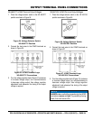
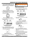
1. Place the voltage selector switch in the desired
voltage position (Figure 38)..
Figure 38. Voltage Selector Switch
1. Place the engine speed switch (Figure 39) in the
(down) position.
Figure 39. Engine Speed Switch (Low)
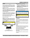
2. Located in the control box is the engine controller
diagnostic switch (Figure 40). Verify that this switch
has been placed in the OFF position (down).
Figure 40. Diagnostic Switch
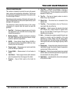
3. Place the in the
position to start the engine (Figure 41).
Figure 41. MPEC Control Switch
(Manual Position)