


PAGE 20 — DCA-10SPX4— OPERATION AND PARTS MANUAL — REV. #0 (02/17/09)
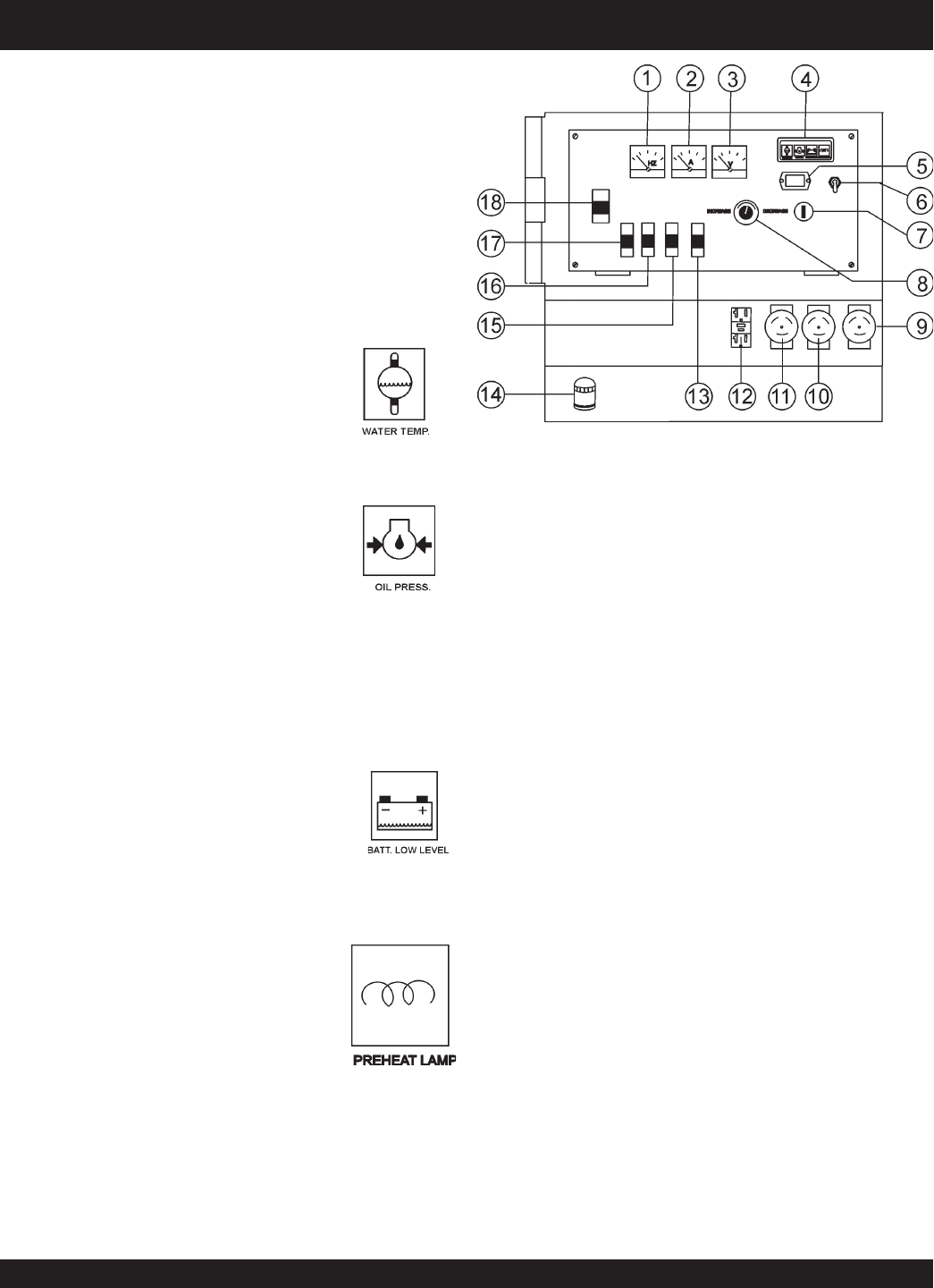
DCA-10SPX4 — GENERATOR CONTROL PANEL
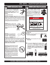
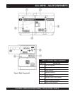
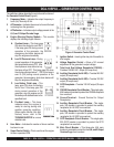
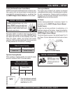
The definitions below describe the controls and functions of
the
Generator Control Panel
(Figure 4).
1. Frequency Meter – Indicates the output frequency in
hertz (Hz). Normally 60 Hz.
2. AC Ammeter – Indicates the amount of current the load
is drawing from the generator.
3. AC Voltmeter – Indicates output voltage present at the
U,O, and V Output Terminal Lugs
.
4. Engine Warning Display Module – This module
displays the following engine failures:
A. Overheat Lamp – This lamp goes
ON when the coolant is over 234
o
F.
If the lamp goes ON during normal
operation of the generator, the
emergency shut-down device will
stop the engine automatically.
B. Low Oil Pressure Lamp – During
normal operation of the generator
this lamp should remain OFF. After
the oil pressure rises after start-up,
the lamp will go OFF. This lamp goes ON when
the oil presure drops below 7.1 PSI.If this lamp is
ever lit (ON) during normal operation of the
generator, the emergency shut-down device will
stop the engine automatically.
C. Low Battery Fluid Lamp – This
lamp goes ON when the battery
fluid is low. If this lamp goes ON
during normal operation of the
generator, stop the engine and fill
the battery with distilled water to the
specified level.
D. Pre-Heat Lamp – This lamp
indicates when the engine is
ready for starting during cold
weather operating condition.
When engine failures (this light
flashes) occur, refer to the
TROUBLESHOOTIG for a more
detailed code.
5. Hour Meter – Indicates the number of hours machine
has been in use.
6. Speed Control Switch –This is used to set the engine
to idle or operation RPM.
Figure 4. Generator Control Panel
7. Ignition Switch – Insert ignition key into this switch to
start engine.
8. Voltage Regulator Control – Allows ±15% manual
adjustment of the generator’s output voltage.
9. Twist Lock Dual Voltage Receptacle (CS6369) –
Provides 120/240 VAC output (45 amps max).
10. Auxillary Receptacle (for L6-30R) – Provides 240 VAC
output (30 amps max).
11. Auxillary Receptacle (for L5-30R) – Provides 120 VAC
output (30 amps max).
12. GFCI Receptacle – Provides 120 VAC output (20 amps
max).
13. CS6369 Receptacle Circuit Breaker - This single-pole,
45A breaker is provided to protect the CS6369 receptacle
from overload.
14. Ground Terminal - Ground Terminal for Output
Receptacles.
15. Auxillary Receptacle Circuit Breaker - This single-
pole, 30A breaker is provided to protect the auxillary
receptacle (for L6-30R) from overload.
16. Auxillary Receptacle Circuit Breaker - This single-
pole, 30A breaker is provided to protect the auxillary
receptacle (for L5-30R) from overload.
17. GFCI Receptacle Circuit Breaker - This single-pole,
20A GFCI breaker is provided to protect the GFCI
receptacle from overload.
18. Main Circuit Breaker – This three-pole, 45A main
breaker is provided to protect the the
U,N, and V Output
Terminal Lugs
from overload.