


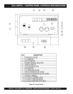
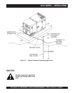

DCA-10SPX3 A.C. GENERATOR — PARTS & OPERATION MANUAL — REV. #2 (01/17/11) — PAGE 25
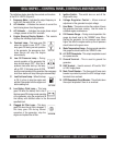
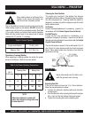
DCA-10SPX3 — CONTROL PANEL, CONTROLS AND INDICATORS
The definitions below describe the controls and functions
of the DCA-10SPX3 (Figure 6):
1. Frequency Meter – Indicates the output frequency in
hertz (Hz). Normally 60 Hz ±1 Hz .
2. AC Ammeter – Indicates the amount of current the
load is being drawn from the generator.
3. AC Voltmeter – Indicates the single phase output
voltage present at the UNV terminals.
4. Engine Warning Display Module – This module
displays the following engine failures:
A. Overheat Lamp – This lamp goes ON
when the coolant is over 215
o
F. If the
lamp goes ON during normal operation
of the generator, the emergency shut-
down device will stop the engine
automatically.
B. Low Oil Pressure Lamp – During
normal operation of the generator this
lamp should remain OFF. After the oil
pressure rises after start-up, the lamp
will go OFF. If this lamp is ever lit (ON)
during normal operation of the generator, the emergency
shut-down device will stop the engine automatically.
C. Low Fuel Level Lamp – When this lamp
is ON, it is time to stop the engine and
add fuel. Remember to let the engine cool
before adding fuel.
D. Low Battery Fluid Lamp – This lamp
goes ON when the battery fluid is low. If
this lamp goes ON during normal operation
of the generator, stop the engine and fill
the battery with distilled water to the
specified level.
E. Clogged Air Filter Lamp – This lamp
goes ON when the air filter is clogged. If
this lamp goes ON during normal
operation of the generator, stop the
engine and replace the air filter.
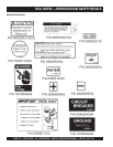
5. Ignition Switch - This switch turns on and off the
engine with a key.
6. Voltage Regulator Control – Allows manual
adjustment of the generator’s output voltage.
7. Hour Meter - This meter monitors the number of hours
the generator has been running. Use this meter to
schedule regular maintenance.
8. Oil Pressure Gauge – During normal operation this
gauge be should read in the “GREEN” zone. When
starting the generator, the oil pressure mark reads
higher, but after the engine warms up the oil pressure
should return to the green zone.
9. Water Temperature Gauge – During normal operation
this gauge be should read in the “GREEN” zone.
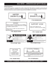
10. A.C. GCFI Receptacle - This output receptacle is used
as a power source.
11. Ground Terminal - This is used to ground the
generator.
12. UNV Terminal - Used to connect AC load for 120V
or 240V single phase.
13. Main Circuit Breaker – This three-pole,20 amp main
breaker is provided to protect the UNV voltage output
terminals from overload.
14. GCFI Receptacle Circuit Breaker - This will shut down
the output receptacle if there in an overload.