


13
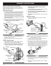
BRUSHCUTTER ASSEMBLY INSTRUCTIONS
Cutting Attachment
Locking Rod
Slot
Locking Rod
Shaft Bushing Hole
Locking Rod Slot
Output Shaft
Bushing
Locking Rod
Output Shaft
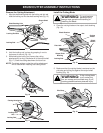
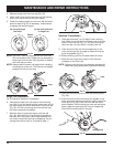
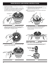
2. Hold the locking rod in place by grasping it next to
the boom of the unit (Fig. 16).
3. While holding the locking rod, remove the cutting
attachment by turning it clockwise off of the output shaft
(Fig. 17). Store the cutting attachment for future use.
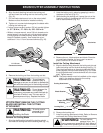
NOTE: The blade retainer under the cutting attachment
will be used when installing the cutting blade.
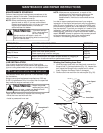
Fig. 15
Fig. 17
Fig. 16
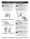
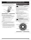
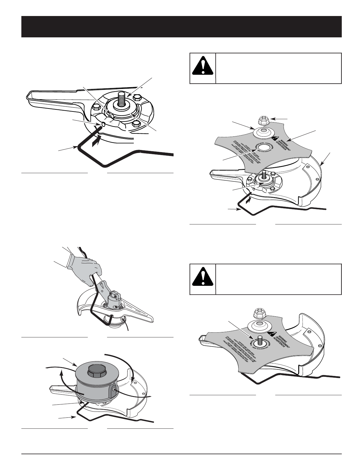
Install the Cutting Blade
4. Place the cutting blade on the output shaft bushing
(Fig. 18).
Shield
Mount
Locking Rod
Cutting
Blade
Blade Retainer
Nut
Output Shaft
Bushing
Pilot Hole
Fig. 18
To avoid serious
personal injury,
always wear gloves while handling or
installing the blade.
WARNING:
Remove the Cutting Attachment
1.
Align the shaft bushing hole with the locking rod slot and
insert the locking rod into the shaft bushing hole (Fig. 15).
Fig. 19
Pilot Step
5. Make sure that the cutting blade is centered on the
pilot step and sitting flat against the output shaft
bushing (Fig. 19).
If the cutting blade
is off-center, the
unit will vibrate and the blade may fly off,
causing possible serious personal injury.
WARNING: