


6
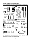
SECTION 3: ASSEMBLING YOUR SNOW THROWER
NOTE: Reference to right or left side of the snow
thrower can be determined from behind the unit in the
operating position.
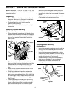
Unpacking
• Remove staples or break glue on the top flaps of
the carton. Remove any loose parts included with
unit (i.e., operator’s manual, etc.).
• Cut corners and lay end of carton down flat.
Remove packing material.
• Roll unit out of carton. Check carton thoroughly for
loose parts.
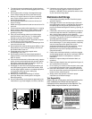
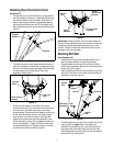
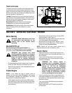
Attaching Handle Assembly
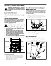
(Use Hardware A)
• Place right handle in position so the flat side of the
handle is against the snow thrower. Secure bottom
hole in handle to snow thrower using hex bolt 3/4”
long and lock washer. Do not tighten at this time.
See Figure 1.
Figure 1
• Place handle tab over the upper hole in handle, so
the curve in the handle tab matches the curve in the
handle. Secure to the snow thrower using 1-3/4”
hex bolt and lock washer. Do not tighten at this
time.
• Attach the left handle in the same manner and do
not tighten at this time.
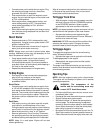
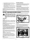
• Place the handle panel in position between the
handles. To hold the handle panel in place, depress
both controls against the handles. While continuing
to hold the right control, release the left control (the
auger control lock will keep left control engaged).
See Figure 2.
• Fasten right side of the handle panel by inserting
two carriage bolts through handle and handle panel
(bolts must go through both the plastic and metal
parts of the handle panel). Secure with cupped
washers (cupped side against handle panel) and
hex nuts.
• Secure the left side of the handle panel in the same
manner.
• Tighten the four hex bolts used to attach the bottom
of the handles to the snow thrower frame.
Figure 2
Attaching Chute Assembly
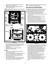
(Use Hardware B)
• Place chute assembly over chute opening, with the
opening in the chute assembly facing the front of
the unit.
• Place chute flange keepers beneath lip of chute
assembly with the flat side down. Insert hex bolt up
through chute flange keeper and chute assembly.
Secure with hex lock nut. See Figure 3.
• After assembling all three chute flange keepers,
tighten all nuts and bolts. Do not overtighten
hardware as it will restrict movement of the
discharge chute.
Figure 3
Handle Tab
Lock Washer
Hex Bolt
1-3/4”
Hex Bolt
3/4”
Carriage
Bolts
Cupped
Washer
Hex Nut
Handle
Panel
Chute
Assembly
Hex Bolts
Hex Lock
Nut
Chute Flange
Keepers