


8
IMPORTANT: Attach the shift rod and clutch cables as follows. THEN CHECK THE ADJUSTMENTS AS
INSTRUCTED, AND MAKE ANY FINAL ADJUSTMENTS NECESSARY BEFORE
OPERATING YOUR
SNOW THROWER. Failure to follow the instructions may cause damage to the snow thrower.
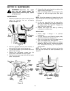
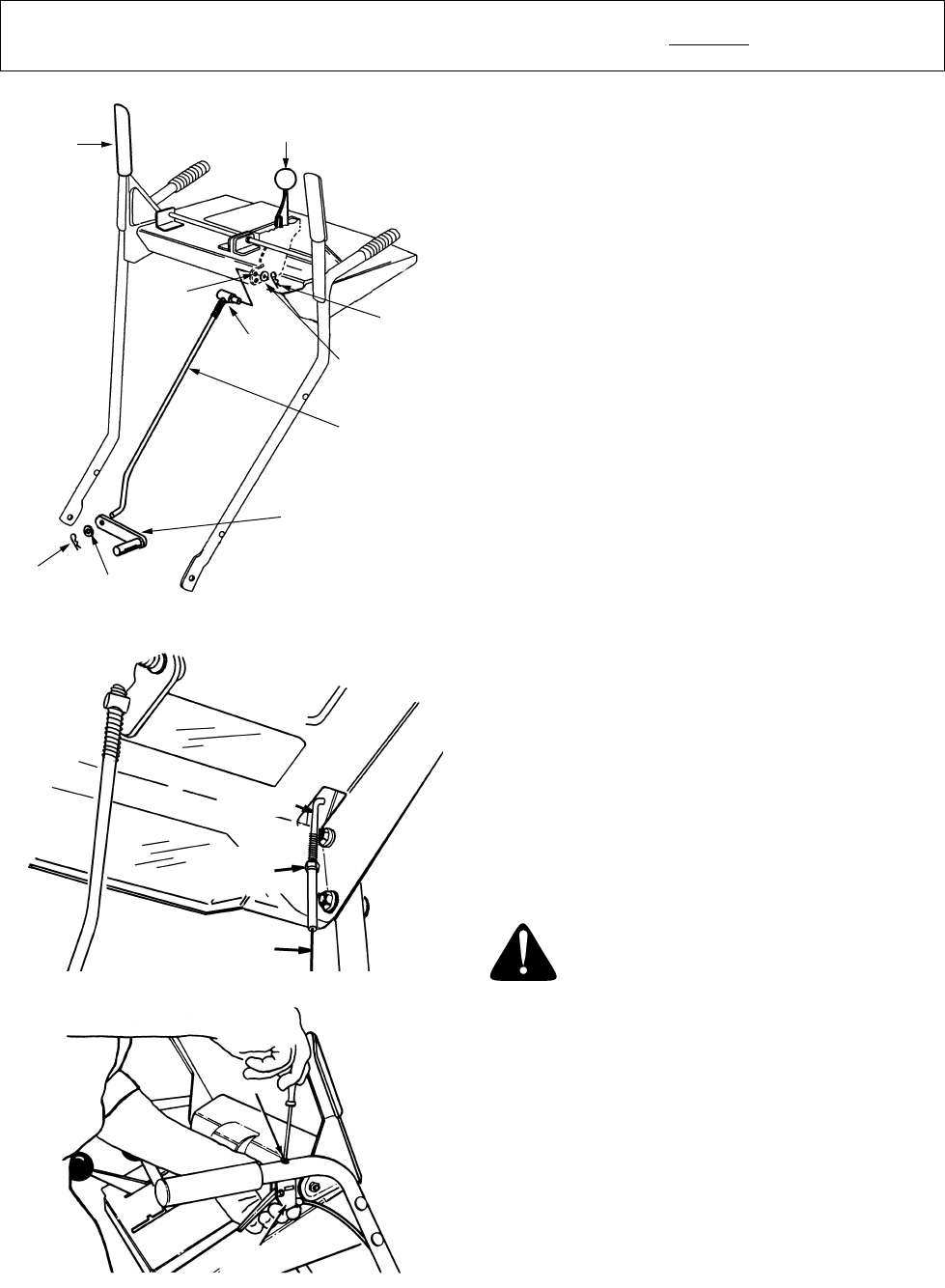
Figure 9
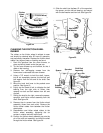
Figure 10
Figure 11
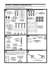
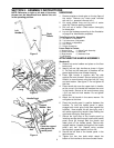
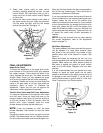
ATTACHING THE SHIFT ROD
(Hardware D)
1. Place the shift lever (on the handle panel) in the
sixth (6) speed position (all the way forward).
2. Place the bent end of the shift rod into the hole
in the shift arm assembly. See figure 9. Secure
with flat washer and hairpin clip.
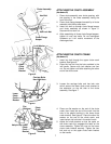
3. Start threading the ferrule onto the other end of
the shift rod. Push down on the shift rod (and
shift arm assembly) as far as it will go.
4. Thread the ferrule onto the shift rod until the
ferrule lines up with the
upper
hole in the shift
lever (beneath the handle panel). Insert the
ferrule into the upper hole in the shift lever from
the left side when adjustment is correct. Secure
with flat washer and hairpin clip.
Make certain to check for correct adjustment of the
shift rod as instructed in the Final Adjustment
section before operating the snow thrower.
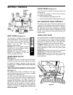
ATTACHING THE CLUTCH CABLES
The “Z” end of the clutch cables are hooked into the
clutch grips on each handle. Attach cables as
follows.
1. Thread the hex jam nuts all the way up the
threaded portion of the “Z” ends of the clutch
cables.
2. Make certain each cable is in groove of cable
roller guides. Place the clutch grip in the raised
(up) position.
3. Thread the cable onto the threaded portion of
the “Z” and until there is no slack in the cable,
but the
cable is NOT tight. Do not overtighten
cable.
See figure 10.
WARNING:
If cable is tightened so
there is tension on the cable with the
clutch grip released, the safety features of
the snow thrower may be overridden.
4. When correct adjustment is reached, tighten the
hex jam nut against the bottom portion of the
cable to lock it in position.
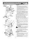
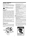
ATTACHING THE TRACK CONTROLS
(Hardware G)
1. Remove the screw from the top of the right
hand track control. Be careful not to lose the flat
weld nut that is inside the control.
2. Place the right track control in position
underneath the right handle. Secure with screw
just removed. See figure 11.
3. Secure the left track control in the same manner.
Traction
Drive
Clutch
Shift Lever
Hairpin
Clip
Flat
Washer
Shift
Rod
Ferrule
Upper
Hole in
Shift
Lever
Hairpin
Clip
Flat
Washer
Shift
Arm
Assembly
“Z” End
Cable
is Straight
Hex Jam
Nut
Right
Track
Control