


7
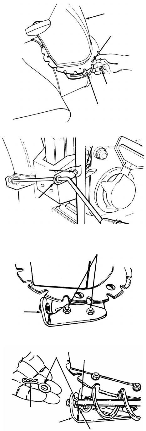
Figure 5
Figure 6
Figure 7
Figure 8
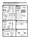
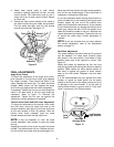
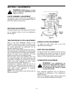
ATTACHING THE CHUTE ASSEMBLY
(Hardware B)
1. Place chute assembly over chute opening, with
the opening in the chute assembly facing the
front of the unit.
2. Place chute flange keepers beneath lip of chute
assembly with the flat side down.
3. Insert hex bolt up through chute flange keeper
and chute assembly as shown in figure 5.
Secure with hex lock nut.
4. After assembling all three chute flange keepers,
tighten all nuts and bolts. Do not overtighten
hardware as it will restrict movement of the
discharge chute.
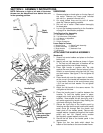
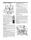
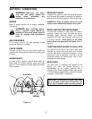
ATTACHING THE CHUTE CRANK
(Hardware C)
1. Insert hex bolt through the upper chute crank
bracket. See figure 6.
2. Place the hex bolt into the hole provided in the
left handle. Secure with lock washer and hex
nut. Do not tighten until after attaching the other
end of the chute crank.
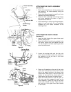
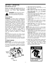
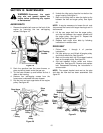
3. Loosen the carriage bolts and hex lock nuts
which secure the lower chute crank bracket to
the extension on the left side of the chute
assembly. See figure 7.
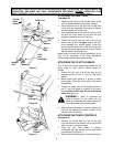
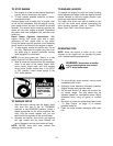
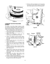
4. Place one flat washer on the end of the chute
crank, then insert the end of the crank into the
hole in the plastic bushing in the lower chute
crank bracket. See figure 8. Place the other flat
washer on the end of the chute crank, and
insert hairpin clip into hole in the end of crank.
5. Adjust the chute bracket so that the spiral on
the chute crank fully engages the teeth on the
chute assembly. Tighten the nuts on the lower
chute crank bracket securely. Tighten the hex
bolt and nut on the upper chute crank bracket
on the handle.
Chute Assembly
Hex Bolt
Hex Lock Nut
Chute Flange
Keeper
Lock Washer
Hex Nut
Hex Bolt
Upper
Chute
Crank
Bracket
Lower
Chute
Crank
Bracket
Carriage Bolts
Hex Lock Nuts
Plastic
Bushing
Lower
Chute
Crank
Bracket
Hairpin Clip
Flat
Washers
Chute
Crank