


FIGURE 14
9
ASSEMBLY INSTRUCTIONS
FIGURE 15
FIGURE 16
FIGURE 17
FIGURE 13
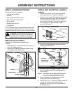
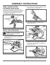
INSTALL THE NEW CUTTING
ATTACHMENT SHIELD MOUNT
Install the cutting attachment shield mount on the
gear housing by installing the three (3) bolts and nuts
removed from the old cutting attachment shield with
a 7/16 wrench. Nuts must be positioned on top for
correct assembly. See Figure 13.
INSTALL THE CUTTING BLADE
WARNING: To avoid serious personal injury,
always wear gloves while handling or
installing the blade.
1. Align the shaft bushing hole with the locking rod
slot and insert the locking rod into the bushing
hole. See Figure 14.
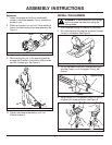
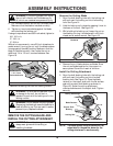
2. Hold the locking rod in place by grasping it next to
the boom of the unit. See Figure 15.
Nuts
Cutting Attachment
Shield Mount
Shaft Bushing Hole
Locking Rod Slot
Output Shaft
Bushing
Locking Rod
Output Shaft
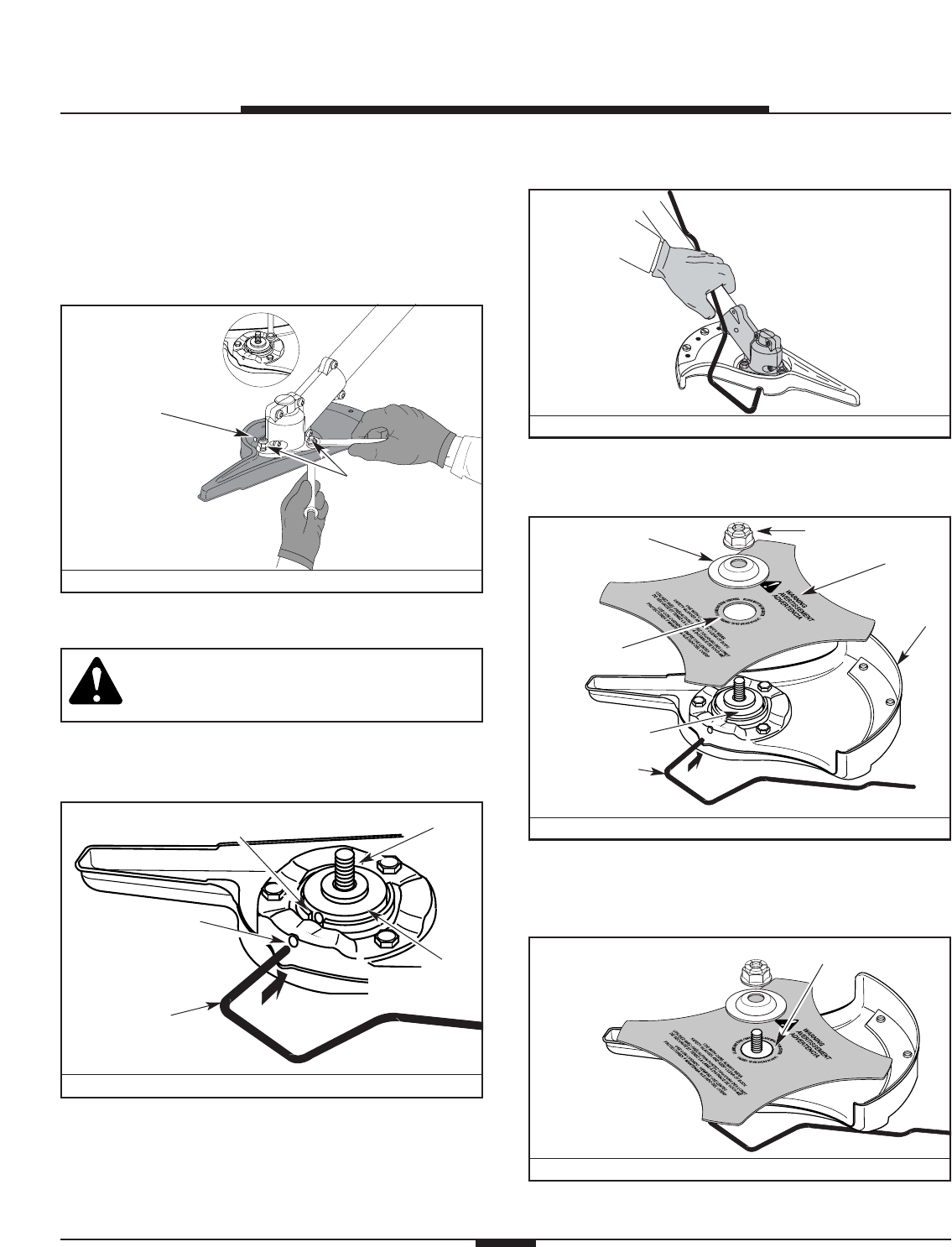
3. Place the cutting blade on the output shaft
bushing. See Figure 16.
Shield
Mount
Locking Rod
Cutting
Blade
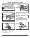
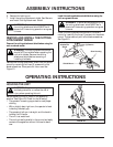
Blade Retainer
Nut
Output Shaft
Bushing
Pilot Hole
4. Make sure that the cutting blade is centered on the
pilot step and sitting flat against the output shaft
bushing. See Figure 17.
Pilot Step