


FIGURE 2
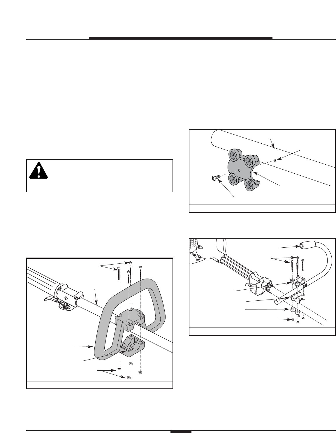
FIGURE 3
ASSEMBLY INSTRUCTIONS
6
INSTALL THE BRUSHCUTTER KIT
The Brush Cutter Kit consists of:
• J-handle and hardware
• Harness
• New cutting attachment mount
• New cutting attachment shield
• Cutting blade
• Blade retainer and nut
• Locking Rod
The D-handle and old cutting attachment shield must
be removed and replaced. All other kit items must be
assembled before using the unit with the cutting blade.
WARNING: To avoid serious personal injury
or damage to the unit, ALL of the items in
the brush cutter kit MUST be installed when
operating the unit with the cutting blade.
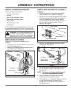
(4) Screws
Shaft
Housing
D-Handle
Bottom Clamp
(4) Nuts
Shaft Grip
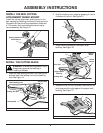
REMOVE THE D-HANDLE
Remove the D-handle before assembling the
J-handle.
1. Remove the four (4) screws and four (4) hex nuts
with a Phillips screwdriver.
2. Remove the D-handle and bottom handle clamp
on the boom shaft. See Figure 1.
FIGURE 1
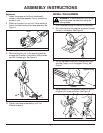
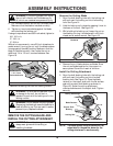
INSTALL AND ADJUST THE J-HANDLE
Installation
1. Remove the screws, nuts and clamp pieces that
were installed on the J-handle for shipping.
2. Lay the unit on its side. On the bottom of the shaft
housing is a pre-drilled hole. With a flat blade or
Torx T-20 screwdriver, insert the anti-rotation
screw through the hole in the bottom clamp and
into the hole in the shaft housing. Tighten
securely. See Figure 2.
Shaft Housing
Anti-rotation screw
Bottom Clamp
Pre-drilled Hole
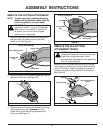
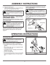
3. Place the J-handle between the top and middle
clamp pieces. See Figure 3.
(4) Screws
Top Clamp
J-Handle
Middle Clamp
Bottom Clamp
Nuts
4. While holding the three pieces together, install the
four (4) screws through the top clamp and into
middle clamp.
NOTE: The holes in the top and middle clamp will
line up only when assembled correctly.
5. Place the clamps and J-handle over the shaft
housing and onto the bottom clamp.
6. Hold each hex nut in the bottom clamp recess with
a finger. Start screws with a large Phillips
screwdriver. Do not tighten until you make the
handle adjustment.