


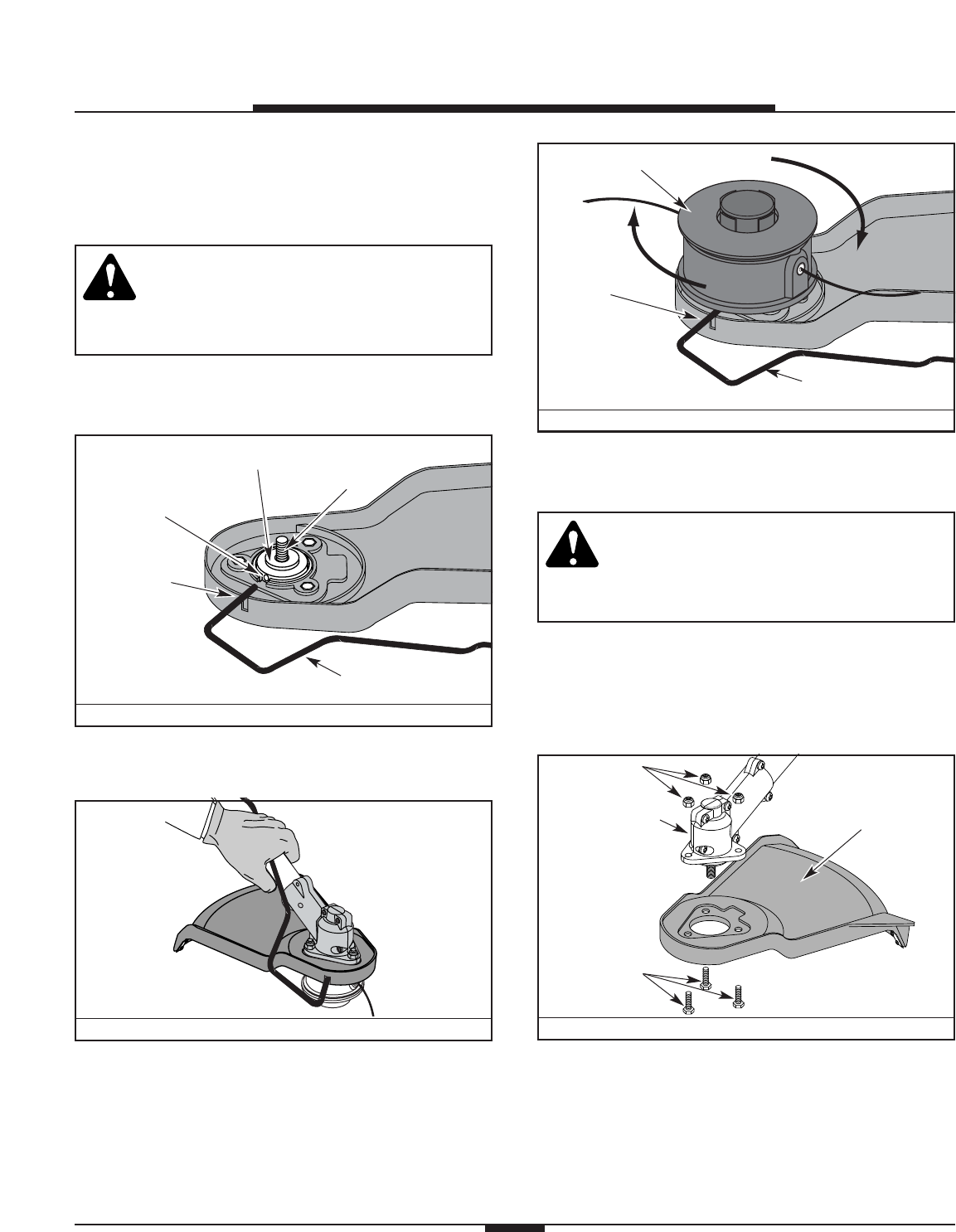
FIGURE 12
FIGURE 9
8
ASSEMBLY INSTRUCTIONS
FIGURE 11
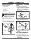
REMOVE THE CUTTING ATTACHMENT
NOTE: To make removing or installing the cutting
blade or cutting attachment easier, place the
unit on the ground or on a work bench.
WARNING: The gear housing gets hot with
use and can result in injury to the operator.
When the unit is turned off it remains hot
for a short time. Do not touch the gear
housing until it has cooled.
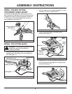
1. Align the shaft bushing hole with the locking rod
slot and insert the locking rod into the shaft
bushing hole. See Figure 9.
Shaft Bushing Hole
Locking Rod
Slot
Output Shaft Bushing
Locking Rod
Output Shaft
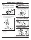
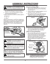
2. Hold the locking rod in place by grasping it next to
the boom of the unit. See Figure 10.
3. While holding the locking rod, remove the cutting
attachment by turning it clockwise off of the
output shaft. Store the cutting attachment for
future use. See Figure 11.
Cutting Attachment
Locking Rod
Slot
Locking Rod
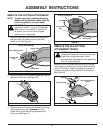
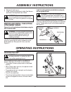
REMOVE THE OLD CUTTING
ATTACHMENT SHIELD
WARNING: You MUST remove the cutting
attachment shield (on the existing unit) and
install the cutting attachment mount
(provided with the blade kit) when operating
the unit as a brushcutter.
Remove the cutting attachment shield from the gear
housing by the removing the three (3) bolts and nuts
with a 7/16 wrench. Keep the hardware to use while
installing the new cutting attachment shield mount.
See Figure 12.
Bolts
Cutting Attachment
Shield
Gear Housing
Nuts
FIGURE 10