


12
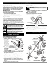
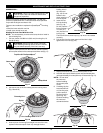
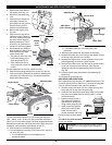
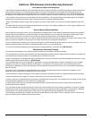
3. Remove the screw behind
the engine cover (Fig. 41).
4. Disconnect the spark plug
wire.
5. Clean dirt from around the
spark plug. Remove the
spark plug from the cylinder
head by turning a 5/8 in.
socket counterclockwise.
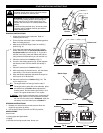
6. Remove the engine cover
(Fig. 40).
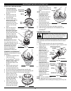
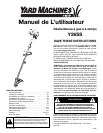
7. Clean dirt from around the
rocker arm cover. Remove
the screw holding the rocker
arm cover with a large flat
blade screwdriver or Torx T-
25 bit (Fig. 42). Remove the
rocker arm cover and gasket.
8. Pull the starter rope slowly to
bring the piston to the top of its
travel, (known as top dead
center). Check that:
• The piston is at the top of its
travel while looking in the
spark plug hole (Fig. 42)
• Both rocker arms move
freely, and both valves are
closed
If these statements are not true, repeat this step.
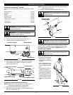
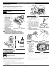
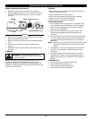
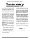
9. Slide the feeler gauge between the rocker arm and the
valve return spring. Measure the clearance between the
valve stem and rocker arm (Fig. 43). Measure both the
intake and exhaust valves.
The recommended clearance for both intake and exhaust is
.003 – .006 in. (.076 – 0.152 mm). Use a standard automotive
.005 in. (0.127 mm) feeler gauge. The feeler gauge should slide
between the rocker arm and valve stem with a slight amount of
resistance, without binding. See Figures 43 and 44.
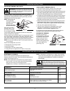
10. If the clearance is not within specification:
a. Turn the adjusting nut using a 5/16 inch (8 mm) wrench or
nut driver (Fig. 44).
• To increase clearance, turn the adjusting nut
counterclockwise.
MAINTENANCE AND REPAIR INSTRUCTIONS
Fig. 44
• To decrease clearance, turn the adjusting nut
clockwise.
b. Recheck both clearances, and adjust as necessary.
11. Reinstall the rocker arm cover using a new gasket. Torque
the screw to 20–30 in•lb (2.2–3.4 N•m).
12. Reinstall the engine cover. Check alignment of the cover
before tightening the screws. Tighten screws.
13. Reinstall the muffler cover. Slip the rear tab on the muffler
cover into the engine cover rear slot. Then slide the
remaining slots into the tabs until they snap into place
(Fig. 39).
14. Check the spark plug and reinstall. See Replacing the
Spark Plug.
15. Replace the spark plug wire.
REPLACING THE SPARK PLUG
Use a replacement part number 791-180852B spark plug. The
correct air gap is 0.025 in. (0.655 mm.). Remove the plug after
every 25 hours of operation and check its condition.
1. Stop the engine and allow it to cool. Grasp the plug wire
firmly and pull the cap from the spark plug.
2. Clean dirt from around the spark plug. Remove the spark
plug from the cylinder head by turning a 5/8 in. socket
counterclockwise.
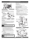
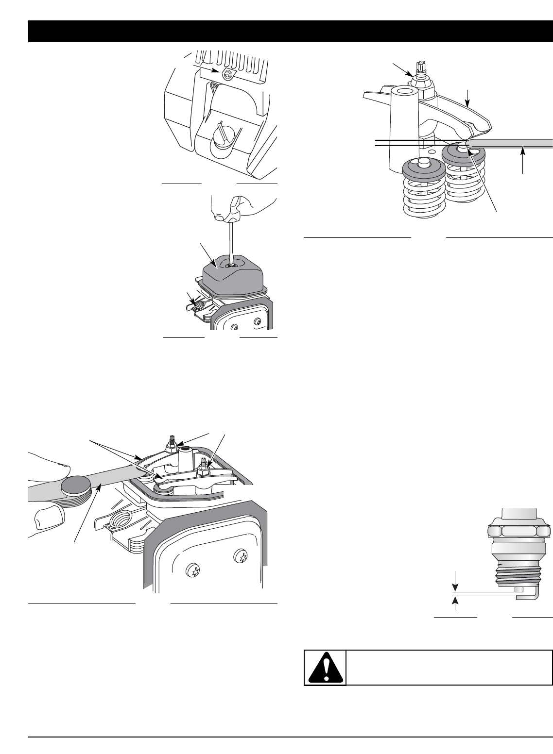
3. Replace cracked, fouled or
dirty spark plug. Set the air
gap at 0.025 in. (0.655 mm.)
using a feeler gauge (Fig. 45).
4. Install a correctly-gapped
spark plug in the cylinder
head. Turn the 5/8 in.
socket clockwise until snug.
If using a torque wrench torque
to:
110-120 in.•lb. (12.3-13.5 N•m)
Do not over tighten.
Feeler Gauge
Adjusting Nut
Rocker Arm
.003–.006 in.
(.076–.152 mm)
Valve Stem
Screw
Fig. 41
Rocker
Arm
Cover
Fig. 42
Spark
Plug
Hole
Adjusting Nuts
Feeler Gauge
Rocker Arms
Fig. 43
INTAKE
EXHAUST
0.025 in.
(0.655 mm.)
Fig. 45
WARNING: Do not sand blast, scrape or clean
electrodes. Grit in the engine could damage the
cylinder.