


5
SECTION 2: ASSEMBLING YOUR SNOW THROWER
Unpacking
• Remove staples or break glue on the top flaps of
the carton. Remove any loose parts included with
unit (i.e., Operator’s Manual, etc).
• Cut along corners and lay end of carton down flat.
Remove packing material.
• Roll unit out of carton. Check carton thoroughly for
loose parts before discarding.
Before Assembly
WARNING: Disconnect spark plug wire
and ground it against the engine to prevent
unintended starting.
NOTE: All references to right or left side of the snow
thrower are determined from behind the unit in the
operating position.
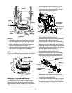
Assembly Tips: For convenience in assembly,
remove the chute from the carton and lay it on top of the
engine. Do not unwrap the chute till you have installed
the handle panel and the clutch cables.
Attaching the Handle
WARNING: Disconnect the spark plug
wire and ground it against the engine to
prevent unintended starting.
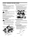
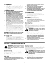
• Remove the two plastic wing nuts, two cupped
washers, a carriage bolt on the right side and an
eyebolt on the left side from the lower handle. See
Figure 1.
• Raise upper handle assembly (in the direction
shown in Figure 1) and align with lower handle.
Figure 1
NOTE: Make sure cables are set in the cable roller
guides in the lower rear of the snow thrower .
• Secure the upper handle to the lower handle with
the hardware removed earlier.
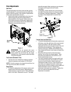
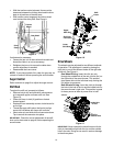
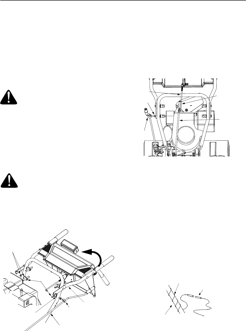
• Adjust eyebolt on the chute directional control so
the control rod does not contact the engine. Move
the hex nut against the handle in order to adjust.
Retighten the wing nut to secure the chute
directional control in this position. See Figure 2.
Figure 2
Assembling the Shift Rod
• Slide the shift rod connector down over the end of
the lower shift rod. Tap the connector until it locks
on the lower shift rod.
NOTE: If the connector is not properly assembled, the
shift rod will pivot and you will not be able to shift gears
or change directions.
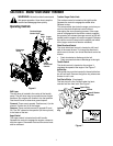
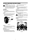
Connecting Headlight
• Unwrap the headlight wire which is attached to the
headlight, beneath the handle panel. Wind it
around the right handle several times to remove
excess slack in the wire. See Figure 3.
• Plug the wire from the headlight into the wire lead
coming from the right side of the engine,
underneath the fuel tank.
Figure 3
Lower Handle
Upper
Handle
Remove
these
Remove
eye bolt
Remove carriage
bolt & washer
Remove
washer
Raise handle
this way
Shift Rod
Upper
Shift Rod
Lower
Shift Rod
Connector
Hex Nut
Eyebolt
Lamp Wire
Alternator
Lead
Right Handle