


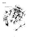
10
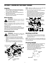
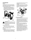
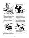
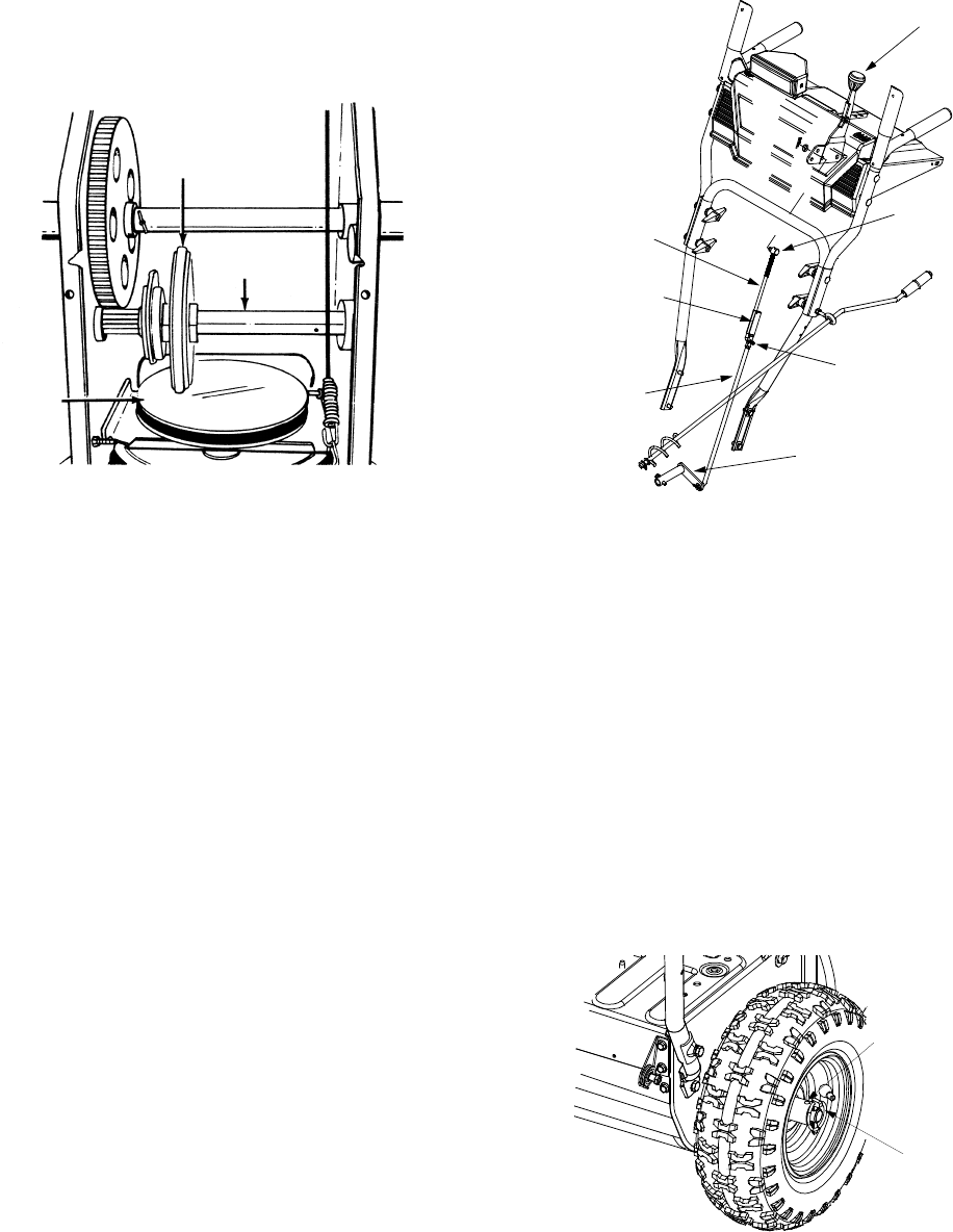
• With the traction control released, there must be
clearance between the friction wheel and the drive
plate in all positions of the shift lever.
• With traction control engaged, the friction wheel
must contact the drive plate. See Figure 9.
Figure 9
If adjustment is necessary:
• Loosen the jam nut on the traction drive cable and
thread the cable in or out as necessary.
• Retighten the jam nut to secure the cable when
correct adjustment is reached.
• Reassemble the frame cover.
NOTE: If you placed plastic film under the gas cap, be
certain to remove it before operating the snow thrower.
Auger Control
Refer to details on page 6 to adjust the auger control.
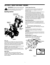
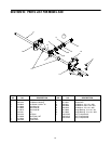
Shift Rod
To adjust the shift rod, proceed as follows.
• Remove hairpin clip and slide shift rod connector
up to separate upper and lower shift rod. See
Figure 10.
• Place shift lever in sixth (6) position or fastest
forward speed.
• Rotate shift arm assembly counter clockwise as far
as it will go.
• Thread the upper shift rod on the ferrule to align
upper shift rod elbow with lower shift rod hole.
• Insert cotter pin and slide shift rod connector down.
Tap to secure the connector into place.
IMPORTANT: Check for correct adjustment of the shift
lever rod as instructed on page 6, before operating the
snow thrower.
Figure 10
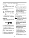
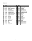
Drive Wheels
The wheels may be adjusted for two different methods
of operation. The adjustment is made by placing the
click pins in one of two different holes on the right side
of the unit. See Figure 11.
One Wheel Driving: Insert the click pin only
through the outside hole of the axle (not the rim) on
the right side of the snow thrower. This position
gives power drive to the left wheel only, making the
unit easier to maneuver.
Both Wheels Driving: Insert the click pin through
the hole in the hub of the rim and the inside hole on
the snow thrower’s right axle. This position is good
for heavy snow as there is power drive in both
wheels.
Figure 11
IMPORTANT: Never operate the snow thrower with the
click pin inserted through both the rim and the outside
hole in the axle. Doing so can result in serious damage
to the drive system.
Friction
Wheel
Gear Shaft
Drive
Plate
Shift
Lever
Ferrule
Upper
Shift Rod
Hairpin
Clip
Shift Rod
Connector
Lower
Shift Rod
Shift Arm
Assembly
Inside Hole
in Axle
Click Pin
in Outside Hole