


12
SECTION 7: SERVICING YOUR SNOW THROWER
WARNING: Before servicing, repairing,
or inspecting, disengage all clutch levers
and stop engine. Wait until all moving parts
have come to a complete stop. Disconnect
spark plug wire and ground it against the
engine to prevent unintended starting.
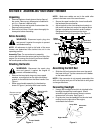
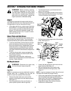
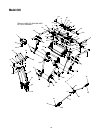
Augers
The augers are secured to the spiral shaft with two
shear bolts and hex lock nuts. If the snow thrower hits
a foreign object or ice jam, hex bolts will shear.
• If the augers will not turn, check to see if the bolts
have sheared. Two replacement shear bolts and
hex lock nuts have been provided with the snow
thrower. For future use, order part number 710-
0890A (shear bolt 5/16-18 x 1.5") and 712-0429
(hex lock nut 5/16-18).
Shave Plate and Skid Shoes
The shave plate and skid shoes on the bottom of the
snow thrower are subject to wear. They should be
checked periodically and replaced when necessary.
• To remove skid shoes, remove the four carriage
bolts, bell washers and hex nuts which attach
them to the snow thrower. Reassemble new skid
shoes with the four carriage bolts, bell washers
(cupped side goes against skid shoes) and hex
nuts. Make certain the skid shoes are adjusted to
be level.
• To remove shave plate, remove carriage bolts,
bell washers and hex nuts which attach it to the
snow thrower housing.
• Reassemble new shave plate, making sure
heads of the carriage bolts are to the inside of the
housing. Tighten securely.
Belt Replacement
WARNING: Disconnect the spark plug
wire from the spark plug and ground.
Auger Belts
NOTE: It is necessary to remove both belts in order to
change either one. If changing just one belt, be
certain to check the condition of the other belt.
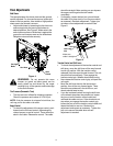
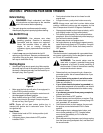
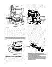
• Remove the plastic belt cover in front of the
engine by removing the two self-tapping screws.
See Figure 14.
• Drain the gasoline from the snow thrower, or
place a piece of plastic under the gas cap.
• Tip the snow thrower up and forward so that it
rests on the housing.
• Remove six self-tapping screws from the frame
cover underneath the snow thrower. See Figure
14 for the location of the hardware.
Figure 14
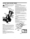
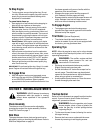
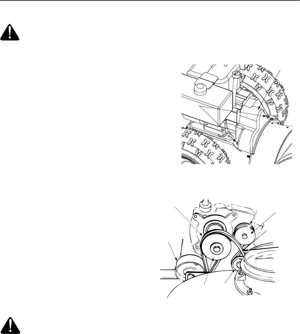
• Roll the front and rear auger belts off the engine
pulley. See Figure 15.
Figure 15
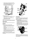
• Unhook the idler spring from the hex bolt on the
auger housing. See Figure 16.
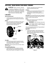
• Back out the stop bolt to allow belts to slip
between the bolt and the auger pulley. See
Figure 17.
NOTE: It may be necessary to loosen the six hex nuts
that fasten the frame to the auger housing.
• Lift the rear auger belt from the auger pulley, and
slip belt between the support bracket and the
auger pulley. See Figure 16. Repeat this step for
front auger belt (except models 600/610E).
• Replace both auger drive belts by following
instructions in reverse order.
Self-Tapping
Screws
Belt
Cover
Rear Auger
Drive
Belt
Engine
Pulley
Front Auger
Idler
Pulley
Idler
Pulley
Engine
Pulley
Belt
Belt