


21
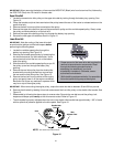
IMPORTANT:
When removing the battery, disconnect the NEGATIVE (Black) wire from its terminal first, followed by
the POSITIVE (Red) wire. Re-install in reverse order.
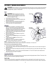
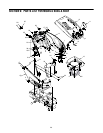
Upper Drive Belt
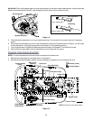
1. Locate the transmission idler pulley on the upper drive belt by looking through the battery tray opening. See
Figure 15.
2. Grasp the bracket and pivot the transmission idler pulley toward the rear of the tractor to release tension on the
upper drive belt.
3. Remove the belt from around the transmission idler pulley.
4. Remove the upper drive belt from around the transmission pulley and the variable-speed pulley. Slowly rotate
the pulley counterclockwise to roll the belt off it.
5. Remove the upper drive belt by pulling it up through the battery tray opening.
6. Reroute the new upper drive belt as shown in Figure 15.
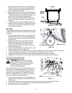
Lower Drive Belt
IMPORTANT:
Note the routing of the lower drive belt
around both the pulleys and the belt keepers before
performing the following steps.
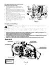
1. Locate the variable-speed pulley through the
battery tray opening. See Figure 15.
2. Remove the variable-speed pulley by loosening the
hex bolt that secures it to the transmission. Use a
second wrench to hold the hex nut on the bottom
side of the pulley.
3. Slide the belt off the variable-speed pulley as you lift
the pulley up and out through the battery tray
opening.
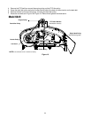
4. Remove the rear idler pulley from the double-idler
bracket while unrouting the belt from around both
the rear and the front idler pulley. See Figure 15.
5. Remove the hex bolt from the center of the engine
pulley and gently lower it off the engine crankshaft.
Be careful not to lose any washers or spacers which
may be on top of the engine pulley.
IMPORTANT:
When remounting the engine pulley, torque the center hex bolt to between 38 and 50 foot-pounds.
6. Remove the drive belt by feeding it from both ends toward the front idler pulley on the double-idler bracket. See
Figure 15.
7. Reassemble by following the above steps in reverse order. Reroute the new belt around the pulleys, belt
keepers and keeper pins exactly as the old one was routed. Refer to Figure 15.
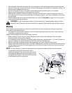
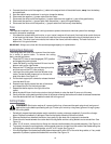
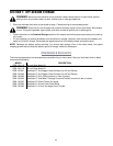
• The drive pedal is properly adjusted when the hole in the double-idler bracket has approximately 1-3/8" of travel
with ten pounds of pressure applied to the drive pedal. See Figure 16.
1. Proper removal of the lower drive belt requires the
removal of several tractor components. Read
through the following procedure prior to
attempting it to determine if you could
successfully complete it. Otherwise, see an
authorized service dealer .
2. While installing replacement belts, it is essential to
follow the same routing map as the original.
IMPORTANT
Double-Idler
Bracket
Idler
Adjuster Rod
Hole
1
-
3
/
8
”
Front of Tractor
NOTE: View shown from above tractor.
Figure 16