


16
1. With the tractor parked on a firm, level surface, place
the deck lift lever in the top notch (highest position)
and rotate the blade nearest the discharge chute so
that it is parallel with the tractor.
2. Measure the distance from the front of the blade tip to
the ground and the rear of the blade tip to the ground.
The first measurement taken should be between 1/4"
and 3/8" less than the second measurement.
Determine the approximate distance necessary for
proper adjustment and proceed, if necessary, to the
next step.
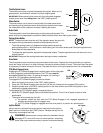
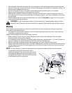
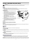
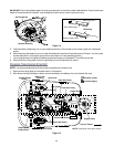
3. Locate the two lock nuts on the opposite side of the
stabilizer bracket. See Figure 9. Tighten the lock nuts
to raise the front of the deck; loosen the lock nuts to
lower the front of the deck.
Side to Side
If the cutting deck appears to be mowing unevenly, a side
to side adjustment can be performed. Adjust if necessary
as follows:
1. With the tractor parked on a firm, level surface, place
the deck lift lever in the top notch (highest position)
and rotate both blades so that they are perpendicular
with the tractor.
2. Measure the distance from the outside of the left
blade tip to the ground and the distance from the
outside of the right blade tip to the ground. Both
measurements taken should be equal. If they’re not,
proceed to the next step.
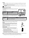
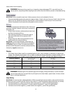
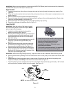
3. Loosen, but do not remove, the hex cap screw on the
left deck hanger bracket. See Figure 10.
4. To balance the deck turn the adjustment gear, located immediately behind the hex cap screw, clockwise/up or
counterclockwise/down. See Figure 10. You will need an adjustable wrench for this step.
5. The deck is properly balanced when both blade tip measurements, taken earlier, are equal.
6. Retighten the hex cap screw on the left deck hanger bracket when proper adjustment is achieved.
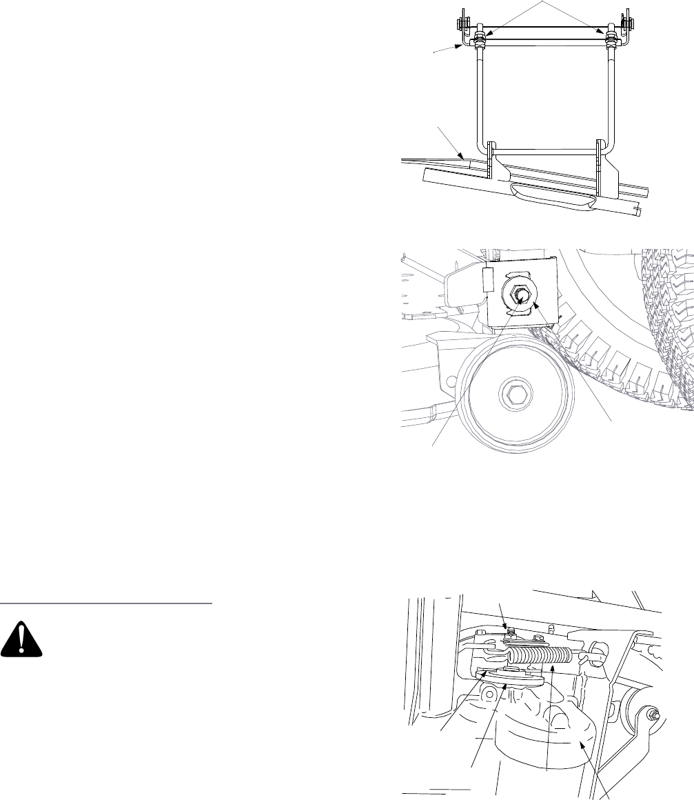
Parking Brake Adjustment
If the tractor does not come to a complete stop when the
brake pedal is completely depressed, or if the tractor’s
rear wheels can roll with the parking brake applied, the
brake is in need of adjustment. The brake disc can be
found on the right side of the transmission in the rear of
the tractor. Adjust if necessary as follows:
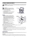
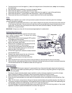
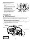
1. Looking at the transmission from the right side of the
tractor, locate the compression spring and brake disc.
See Figure 11.
2. Loosen, but do not remove, the hex nut found on the right side of the brake assembly. See Figure 11.
3. Using a feeler gauge, set the gap between the brake disc and the brake puck at .011".
4. Re-tighten the hex nut loosened earlier.
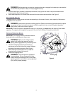
WARNING: Never attempt to adjust the
brakes while the engine is running. Always
disengage PTO, move shift lever into neutral
position, stop engine and remove key to
prevent unintended starting.
Deck
Stabilizer
Brac
ket
Deck
Figure 9
Lock Nut
Hex C
ap Screw
Adjustment Gear
Figure 10
Brake Disc
Hex Nut
Compression
Spring
Set gap
at .011"
NOTE:
View shown from beneath tractor.
Transmission
Figure 11