


19
4. Connect the other end of the negative (-) cable to the engine block of the stalled tractor, away from the battery,
and stand back.
5. Start the stalled tractor and leave it running to charge the battery.
6. Disconnect the negative (-) jumper cable from the tractor.
7. Disconnect the other end of the negative (-) jumper cable from the negative (-) post of the good battery.
8. Disconnect the positive (+) jumper cable from the positive (+) post of the good battery.
9. Disconnect the other end of the positive (+) jumper cable from the formerly dead battery.
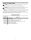
Fuse
Two fuses are installed in your tractor’s wiring harness to protect the tractor’s electrical system from damage
caused by excessive amperage.
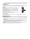
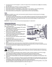
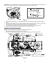
• If the electrical system does not function, or your tractor’s engine will not crank, first check to be certain that one
of the fuses has not blown. One can be found under the hood mounted behind the top of the dash panel on the
support bar. The other fuse is mounted to the inside of the frame, behind the battery. Pull each fuse out to
determine if it is good or blown.
IMPORTANT:
Always use a fuse with the same amperage capacity for replacement.
Cutting Deck Removal
The cutting deck will have to be removed from the tractor
for a variety of service tasks. To remove the cutting
deck, proceed as follows:
1. Place the PTO lever in the disengaged (OFF) position
and engage the parking brake.
2. Lower the deck by moving the deck lift lever into the
bottom notch on the right fender.
3. Remove the PTO belt from around the engine pulley
and from around the PTO idler pulley(s).
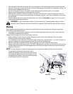
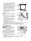
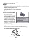
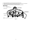
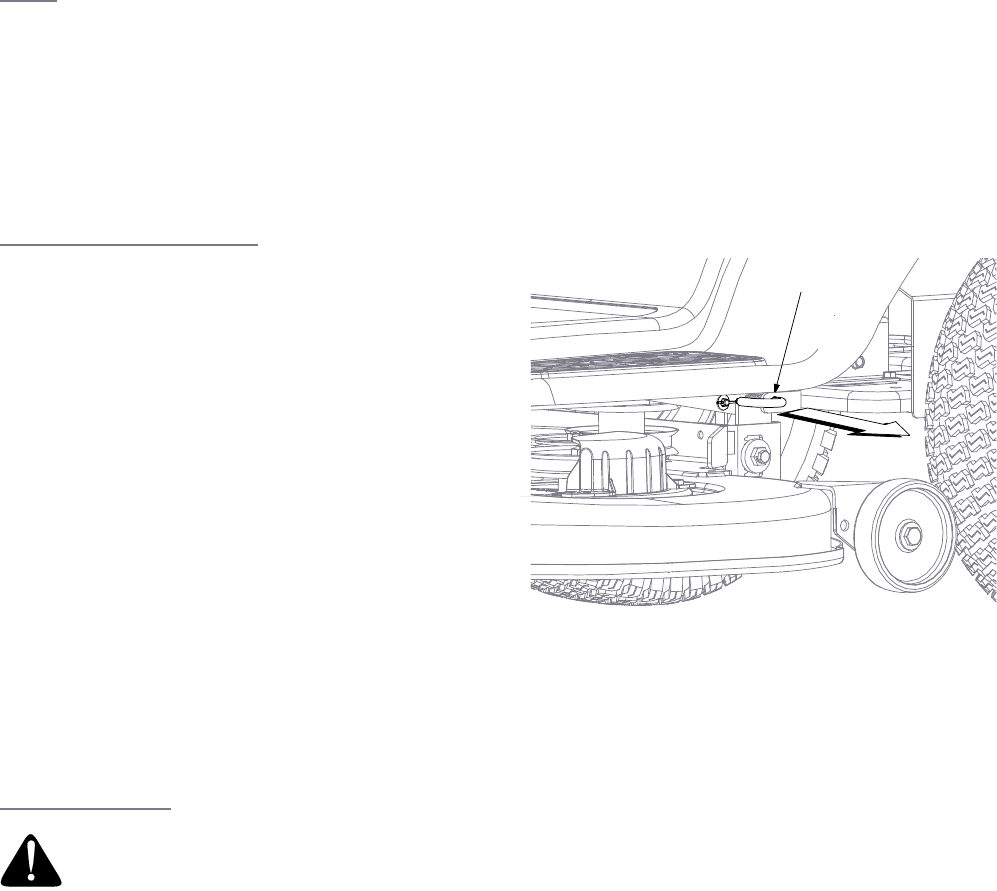
4. Looking at the cutting deck from the left side of the
tractor, locate the deck support pin on the rear left
side of the deck. See Figure 13.
5. Pull the deck support pin outward to release the deck
from the deck lift arm.
6. Rotate the pin slightly toward the rear of the tractor
and release the pin into the hole provided.
7. Repeat the above steps on the right side of the
tractor.
8. Move the deck lift lever into the top notch on the right fender to raise the deck lift arms out of the way.
9. Gently slide the cutting deck toward the front of the tractor allowing the hooks on the deck to release themselves
from the deck stabilizer rod. Do not let the deck fall to the ground.
Cutting Blades
• Periodically inspect the blade adapter and/or spindle for cracks or damage, especially if you strike a foreign
object. Replace immediately if damaged
. Remove the blades following instructions below:
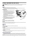
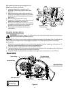
1. Remove the deck from beneath the tractor, then gently flip the deck over to expose its underside.
2. Place a block of wood between the center deck housing baffle and the cutting blade to act as a stabilizer. See
Figure 14.
3. Use a 15/16" wrench, remove the hex flange nut that secures the blade to the spindle assembly. See Figure 14.
4. To properly sharpen the cutting blades, remove equal amounts of metal from both ends of the blades along the
cutting edges, parallel to the trailing edge, at a 25° to 30° angle. See Figure 14.
• If the cutting edge of the blade has already been sharpened to within 5/8" of the wind wing radius, or if any metal
separation is present, replace the blades with new ones. See Figure 14.
WARNING: Shut tractor engine off, remove ignition key, disconnect the spark plug wire(s) and ground
against the engine before proceeding with job. Protect your hands by using heavy gloves or a rag to grasp
the cutting blade
Support Pin
Figure 13