


6
NOTE: References to right or left side of the tiller are
determined from behind the unit in the operating position.
To Remove Unit From Carton
• Remove staples, break glue on top flaps, or cut tape
at carton end and peel along top flap to open carton.
• Remove loose parts included with unit (i.e.,
operator’s manual, etc.).
• Cut corners and lay carton down flat.
• Remove packing material.
• Roll or slide unit out of carton. Check carton
thoroughly for loose parts.
• Extend control cable and lay on the floor. Be careful
not to bend or kink control cable.
IMPORTANT: This unit is shipped without gasoline
or oil in the engine. Be certain to service engine with
gasoline and oil as instructed in the separate engine
manual before operating your machine.
Loose Parts In Carton
• Depth Stake
• Handle Assembly
• Shift Rod
NOTE: All hardware needed for assembly is attached
to the loose parts or the tiller.
Before Assembly
WARNING: Disconnect the spark plug
wire and ground it against the engine to
prevent unintended starting.
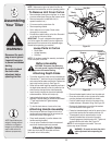
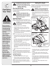
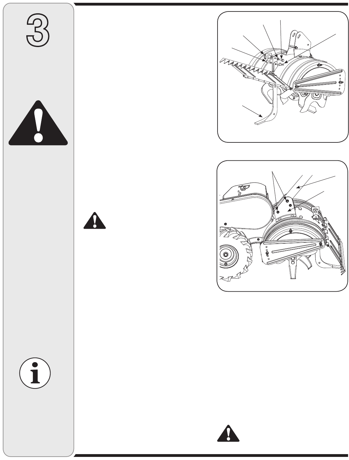
Attaching Depth Stake
• Tip the tiller forward so it rests on front counterweight.
• Unthread the “T” knob from the top of the depth stake
and remove the flat washer and hex bolt. Remove the
hairpin clip from the clevis pin. See Figure 3-1.
• Raise the tine shield hinge flap assembly and insert
the depth stake assembly in the slot (under the tine
shield) and up through the tine shield assembly.
• Insert clevis pin through the tine shield and depth
stake assemblies. Secure with hairpin clip.
• Insert a hex bolt into top hole of the depth stake
assembly. Place flat washer on the hex bolt and thread
“T” knob onto the hex bolt. Tighten securely.
See Figure 3-1.
• Tip the tiller back down so it rests on the tines.
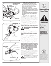
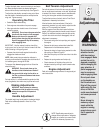
Attaching Handle Assembly
• Remove top two bolts and flange lock nuts from
handle mounting brackets, but do not remove the
bottom bolt and nut. See Figure 3-2.
• Place handle assembly in position between the
handle mounting brackets.
• Line up holes in handle with holes in bracket and
secure with hardware previously removed.
Attaching Clutch Cable
Attach the clutch cable to the handle as follows:
(be careful not to kink the cable)
3
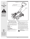
Assembling
Your Tiller
WARNING
Disconnect the spark
plug wire and ground
it against the engine
to prevent unintended
starting.
Be certain to check
the clutch cable
adjustment before
operating the tiller.
Figure 3-1
Figure 3-2
• Remove threaded eyebolt and nut from the cable end.
• Route the clutch cable to the right side of the handle
mounting brackets and underneath the handle.
• Push the cable through the hole in the center of the
handle and snap in the plastic fitting. See Figure 3-3.
• Remove slot head screw, nut, and two flat washers
from the clutch bail. See Figure 3-4.
• Fasten the threaded eyebolt onto bail by securing from
top with slot head screw, flat washers and lock nut.
• Thread eyebolt and nut removed earlier into the
internally threaded tube at the end of the cable.
Thread engagement should be about 3/4”. Tighten nut
against tube at end of cable. See Figure 3-4.
NOTE: Do not overtighten clutch cable. Too much
tension may cause it to break.
WARNING: Be certain to check the clutch
cable adjustment before operating the
tiller.
Clevis Pin
T-Knob
Flat Washer
Hex Bolt
Hairpin Clip
Depth Stake
Remove
Handle
Assembly
Handle
Bracket
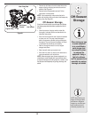
NOTE: Specifications are
subject to change without
notification or obligation.
Images my not reflect your
exact model and are for
reference purposes only.