


6
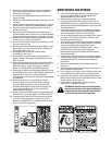
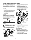
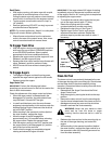
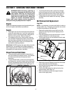
• If not already attached, slip the cables that run from
the handle panel to the chute into the cable guide
located on top of the engine. See Figure 4.
Figure 4
• Unwrap the headlight wire, which is attached to the
headlight beneath the handle panel.
• Wind the headlight wire around the right handle
until excess slack is removed.
• Plug the wire from the headlight into the wire lead
coming from the right side of the engine, beneath
the fuel tank.
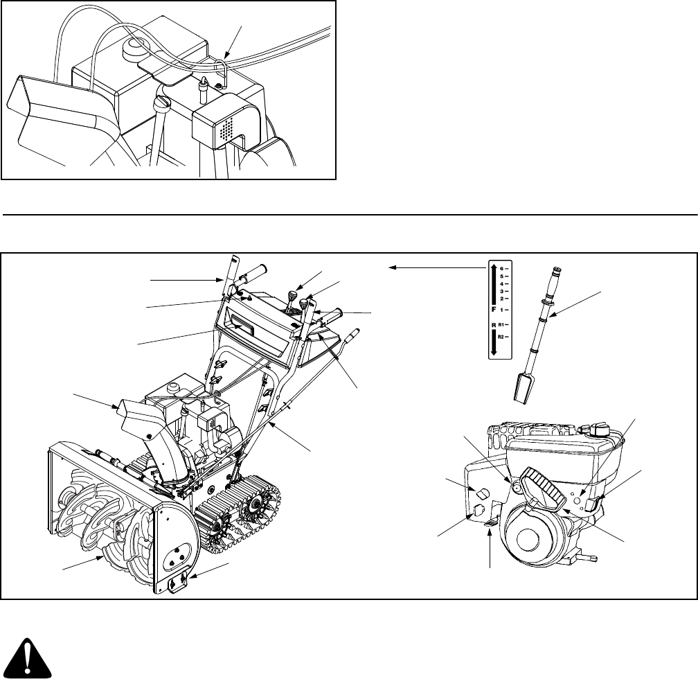
SECTION 3: KNOW YOUR SNOW THROWER
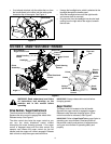
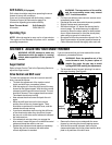
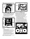
Figure 5
WARNING: Read, understand, and follow
all instructions and warnings on the
machine and in this manual before
operating.
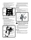
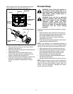
Drive Control / Auger Control Lock
The drive control is located on the right handle.
Squeeze the drive control to engage the wheel drive.
Release to stop. See Figure 5.
The drive control also locks the auger control so you
can turn the chute directional control without
interrupting the snow throwing process. If the auger
control is engaged along with the drive control, the
operator can release the auger control (on the left
handle) and the augers will remain engaged. Release
both controls to stop the augers and track drive.
IMPORTANT:
Always release drive control before
changing speeds.
Auger Control
The auger control is located on the left handle.
Squeeze the auger control to engage the augers.
Release to stop the snow throwing action. (Drive
control must also be released.) See Figure 5.
IMPORTANT:
Refer to Auger Control Test on page 9 prior to
operating your snow thrower. Read and follow all
instructions carefully and perform all adjustments to
verify your snow thrower is operating safely and
properly.
Cable Guide
Drive Control /
Auger Control Lock
Shift Lever
Auger Control
Skid Shoe
Auger
Headlight
Chute
Assembly
Track Steering
Control
Switch
Box
Electric
Starter
Button
Recoil
Starter
Handle
Primer
Choke
Safety
Ignition Key
Throttle
Control
Chute Tilt
Control
Heated Handles
Switch
Chute Directional
Control
Clean-out
Tool