


5
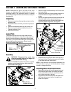
SECTION 2: ASSEMBLING YOUR SNOW THROWER
NOTE: References to right or left side of the snow
thrower are determined from behind the unit in the
operating position. The “operator’s position” is defined
as standing directly behind the snow thrower, facing the
handle panel.
Unpacking
• Remove screws from the top sides and ends of the
shipping crate.
• Set panel aside to avoid tire punctures or personal
injury.
• Remove and discard plastic bag that covers unit.
• Remove any loose parts included with unit (i.e.,
Operator’s Manual, etc.).
• Roll unit out of crate.
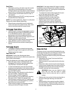
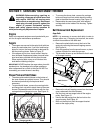
Loose Parts
The augers are secured to the auger shaft with two
shear pins and cotter pins. If you hit a foreign object or
ice jam, the snow thrower is designed so that the pins
may shear. Two replacement shear pins and cotter pins
are provided for your convenience. Store in a safe
place until needed. See Figure 1.
Figure 1
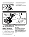
Assembly
WARNING: Disconnect the spark plug
wire and ground it against the engine to
prevent unintended starting.
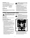
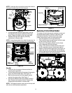
• Remove the lower two plastic wing knobs, cupped
washers and carriage bolts from each side of the
lower handle. See Figure 2.
Figure 2
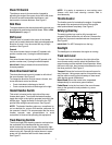
• Raise the upper handle assembly until it locks over
the lower handle.
• Look at the lower rear of snow thrower frame to be
sure both cables are aligned with cable roller
guides.
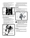
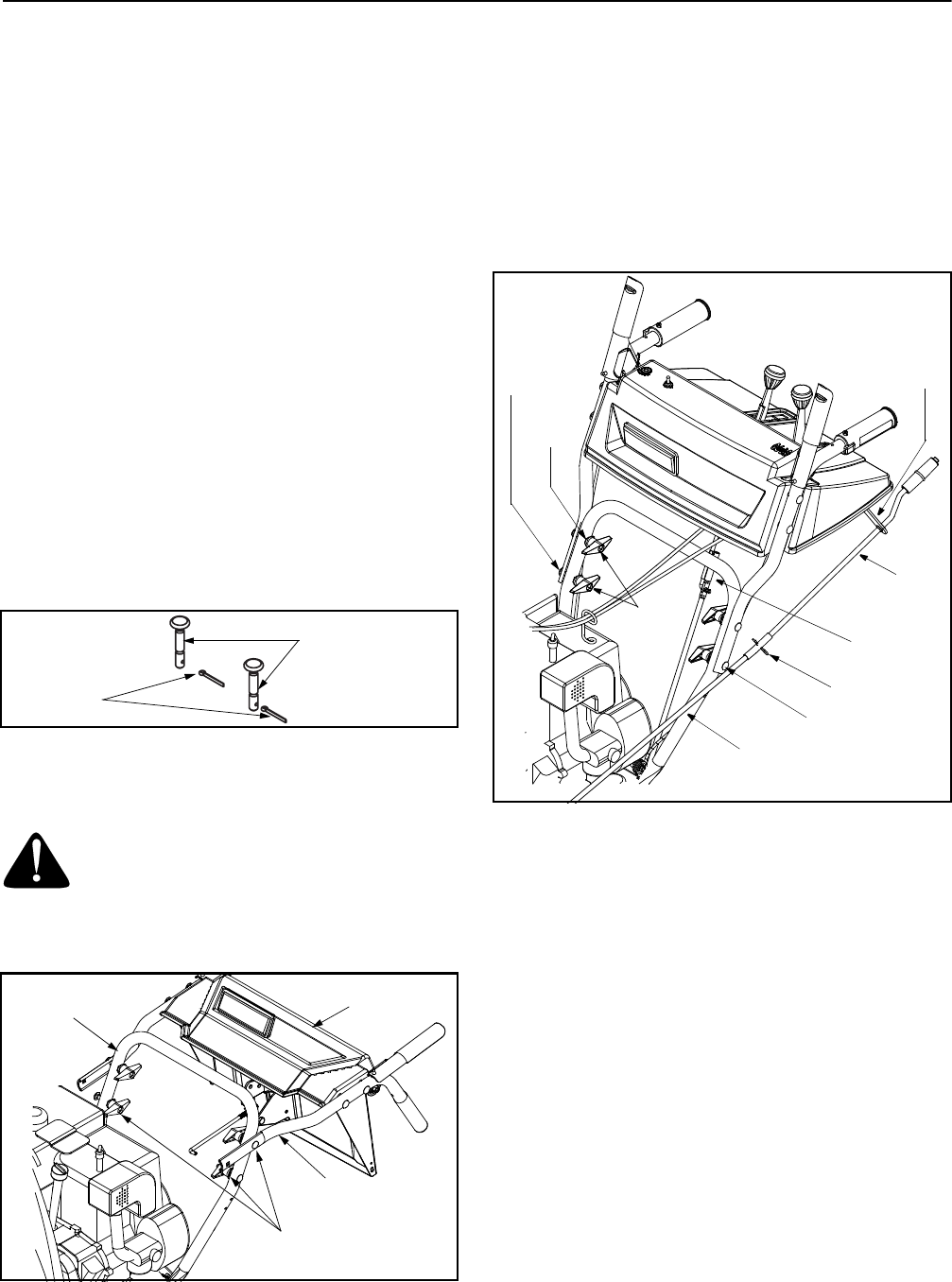
• Secure the upper handle and lower handle with the
two plastic wing knobs, cupped washers and
carriage bolts previously removed and tighten the
upper two plastic wing knobs. See Figure 3.
Figure 3
• Slide the shift rod connector down over the end of
the lower shift rod. Tap the connector until it locks
on the lower shift rod. See Figure 3.
NOTE: If the connector is not properly assembled, the
shift rod will pivot and you will not be able to change
speeds or change directions.
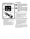
Attaching Chute Directional Control
• Remove the hairpin clip from the upper chute rod
and slide the upper chute rod through the upper
chute rod bracket and into the lower chute rod. A
pair of pliers may help in this job.
• Align the two holes on both chute rods and insert
the hairpin clip removed earlier, through these
holes. See Figure 3.
Shear Pins
Cotter
Pins
Handle
Panel
Lower
Handle
Upper Handle
Wing Knobs,
Washers, & Bolts
Wing
Nut
Upper
Lower Chute Rod
Carriage Bolt
Hairpin Clip
Cupped
Washer
Carriage
Bolt
Chute
Rod
Upper
Chute
Rod
Bracket
Shift Rod
Connector