


13
SECTION 7: SERVICING YOUR SNOW THROWER
WARNING: Before servicing, repairing, or
inspecting, disengage all clutch levers and
stop engine. Wait until all moving parts
have come to a complete stop. Disconnect
spark plug wire and ground it against the
engine to prevent unintended starting.
Always wear safety glasses during operation or
while performing any adjustments or repairs.
Engine
Refer to the separate engine manual packed with your
unit for all engine maintenance procedures.
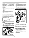
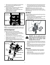
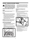
Augers
• The augers are secured to the spiral shaft with two
shear pins and cotter pins. If you hit a hard foreign
object or ice jam, the snow thrower is designed so
that the pins may shear. Refer to Figure 13.
• If the augers will not turn, check to see if the pins
have sheared. Replacement shear pins and cotter
pins have been provided with the snow thrower.
When replacing bolts, spray an oil lubricant into
shaft before inserting new pins.
IMPORTANT:
NEVER replace the auger shear pins with
standard pins. Any damage to the auger gearbox or
other components as a result of doing so will NOT be
covered by your snow thrower’s warranty.
Shave Plate and Skid Shoes
• The shave plate and skid shoes on the bottom of
the snow thrower are subject to wear. They should
be checked periodically and replaced when
necessary.
• To remove skid shoes, remove four carriage bolts
and flange lock nuts which attach them to the snow
thrower. Reassemble new skid shoes with the four
carriage bolts and flange lock nuts. See Figure 13.
Figure 13
• To remove the shave plate, remove the carriage
bolts and flange lock nuts which attach the shave
plate to the snow thrower housing. See Figure 13.
• Reassemble the new shave plate, with heads of
carriage bolts to the inside of the housing. Tighten
securely.
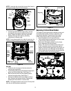
Belt Removal And Replacement
Auger Belts
NOTE: It is necessary to remove both belts in order to
change either one. If changing just one belt, be certain
to check the condition of the other belt.
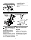
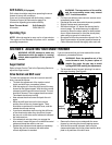
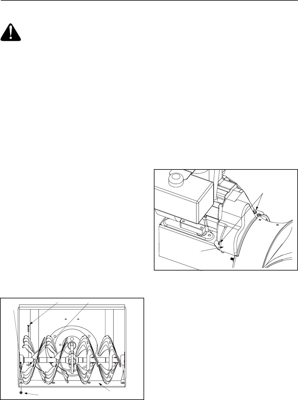
• Remove the plastic belt cover at the front of the
engine by removing the two self-tapping screws.
See Figure 14.
• Drain the gasoline from the snow thrower, or place
a piece of plastic film under the gas cap.
• Tip the snow thrower up and forward so that it rests
on its auger housing.
Figure 14
• Remove the six self-tapping screws from the frame
cover underneath the snow thrower.
• Roll the front and rear auger belts off the engine
pulley. See Figure 15.
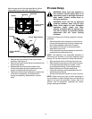
• Unhook the idler spring from the hex bolt on the
auger housing. See Figure 16.
• Back out the stop bolt until the support bracket
rests on the auger pulley.
Shear Pin
Carriage
Bolt
Cotter Pin
Flange Lock Nut
Shave
Plate
Self-Tapping
Screw
Belt Cover