


11
SECTION 5: MAKING ADJUSTMENTS
WARNING: Never attempt to clean chute
or make any adjustments while engine is
running.
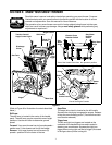
Traction Drive Clutch
Refer to the Final Adjustment section of the Set-Up
Instructions to adjust the traction drive clutch. To check
the adjustment, proceed as follows:
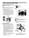
• With the snow thrower tipped forward (be certain to
drain the gasoline or place plastic film under the
gas cap if the snow thrower has already been
operated), remove the frame cover underneath the
snow thrower by removing six self-tapping screws.
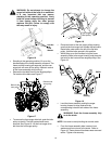
• With the traction drive clutch released, there must
be clearance between the friction wheel and the
drive plate in all positions of the shift lever.
• With the traction drive clutch engaged, the friction
wheel must contact the drive plate (Figure 20).
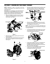
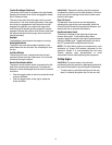
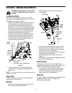
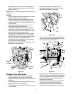
• If adjustment is necessary, loosen the jam nut on
the traction drive cable and thread the cable in or
out as necessary. See Figure 9.
Figure 9
• Tighten the jam nut to secure the cable when
correct adjustment is reached. Reassemble the
frame cover.
NOTE: If you placed plastic under the gas cap, be
certain to remove it.
Auger Clutch
To adjust the auger clutch, refer to Final Adjustment
section of Set-Up Instructions.
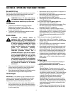
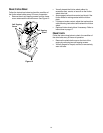
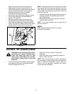
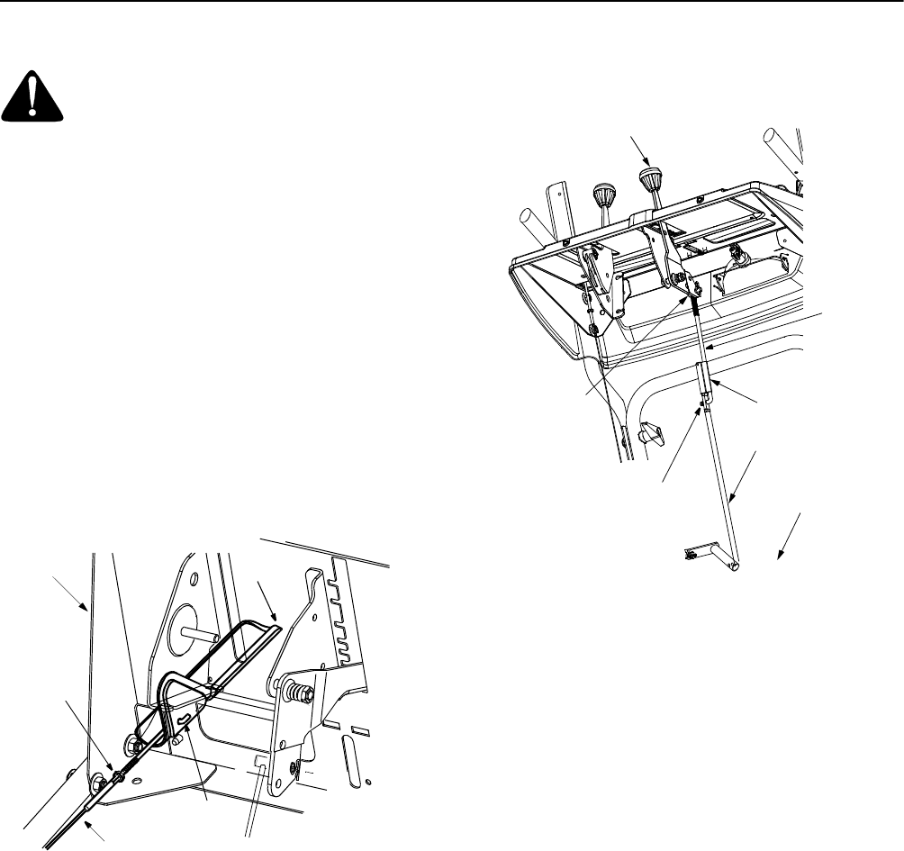
Shift Rod
• Remove the hairpin clip and flat washer from the
shift handle under the handle panel.
• Place shift lever in sixth (6) position or fastest
forward speed.
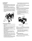
Figure 10
• Push shift arm assembly down as far as it will go.
• Rotate the ferrule up or down on the shift rod as
necessary until the ferrule lines up with the upper
hole in the shift lever. See Figure 10.
• Insert ferrule from the left side of the snow thrower
into the upper hole in shift lever.
• Reinstall the hairpin clip and the washer. See
Figure 10.
• Make certain to check for correct adjustment before
operating the snow thrower.
Chute Assembly
The distance snow is thrown can be adjusted by
adjusting the angle of the chute assembly. Refer to the
“Know Your Snow Thrower” section on page 7.
• The remote chute control cables have been pre-
adjusted at the factory. Move the remote chute
lever on the control panel back and forward to
adjust angle of the chute asssembly.
Slide Shoe
The space between the shave plate and the ground can
be adjusted. Refer to Figure 7 on page 6 for
instructions on adjustment.
Clutch
Grip
Hex Jam
(Thread
here)nut
Cable is straight
but not tight
Z Fitting
(Viewed from under the handle panel)
Handle
Panel
Nut
Shift Lever
Shift Arm
Hairpin
Clip
Lower
Clutch Rod
Upper
Connector
Shift
Rod
Shift
Rod
Ferrule