


5
SECTION 2: ASSEMBLING YOUR SNOW THROWER
NOTE: Reference to right or left side of the snow
thrower in this manual is from behind the unit in the
operating position.
IMPORTANT:
After assembling, check the adjustments
as instructed on page 6 before operating your snow
thrower. Failure to follow the instructions may cause
damage to the snow thrower and void warranty.
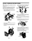
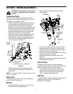
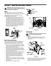
• Remove the lower two plastic wing nuts, cupped
washers and carriage bolts from each side of the
lower handle. See Figure 1.
Figure 1
• Raise the upper handle assembly until it locks over
the lower handle.
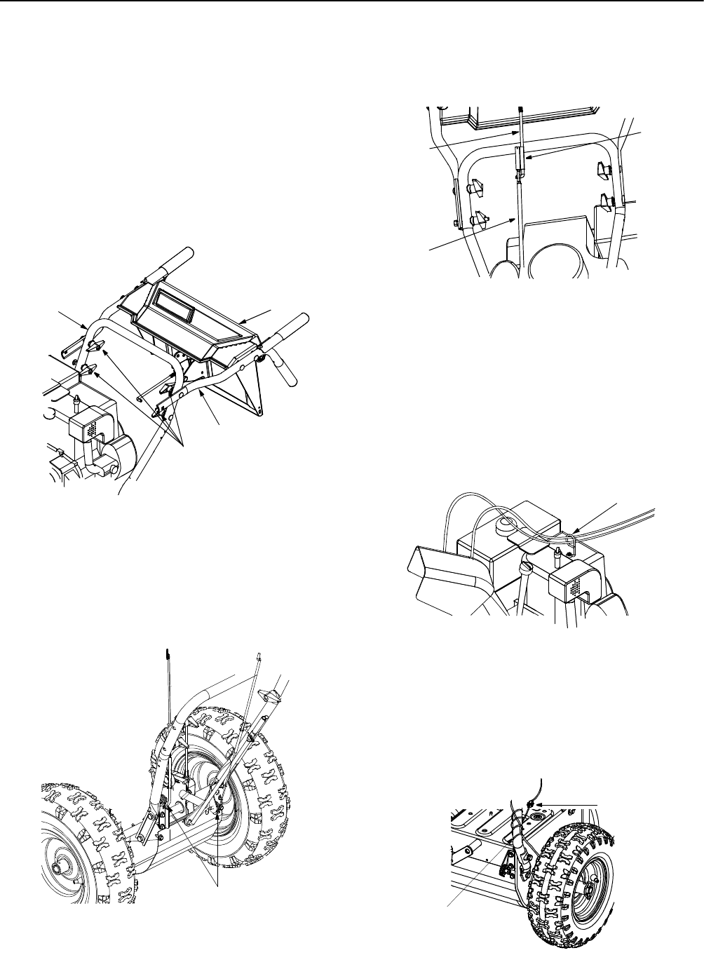
• Look at lower rear of snow thrower frame to be sure
both cables are aligned with cable roller guides.
See Figure 2.
Figure 2
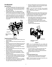
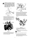
• Secure the upper handle and lower handle on each
side with two plastic wing nuts, cupped washers
and carriage bolts removed earlier. See Figure 3.
Figure 3
• Slide the shift rod connector down over the end of
the lower shift rod. See Figure 3. Tap the connector
until it locks on the lower shift rod.
NOTE: If the connector is not properly assembled, the
shift rod will pivot and you will not be able to shift gears
or change directions.
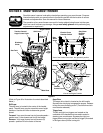
• If not already attached, slip the cables that run from
the handle panel to the chute into the cable guide
on top of the engine. See Figure 4.
Figure 4
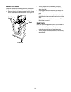
• Unwrap the headlight wire which is attached to the
headlight, beneath the handle panel. Wind the
headlight wire around the right handle until excess
slack is removed. See Figure 5.
• Plug the wire from the headlight into the wire lead
coming from the right side of the engine,
underneath the fuel tank. See Figure 5.
Figure 5
Wing Nuts,
Washers
and Bolts
Lower Handle
Upper Handle
Handle Panel
Check cables
on roller guides
Cable Roller
Guides
Connector
Upper
Lower
Shift Rod
Shift Rod
Shift Rod
Cable Guide
Alternator Lead
Lamp Wire