


9
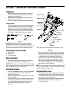
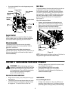
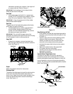
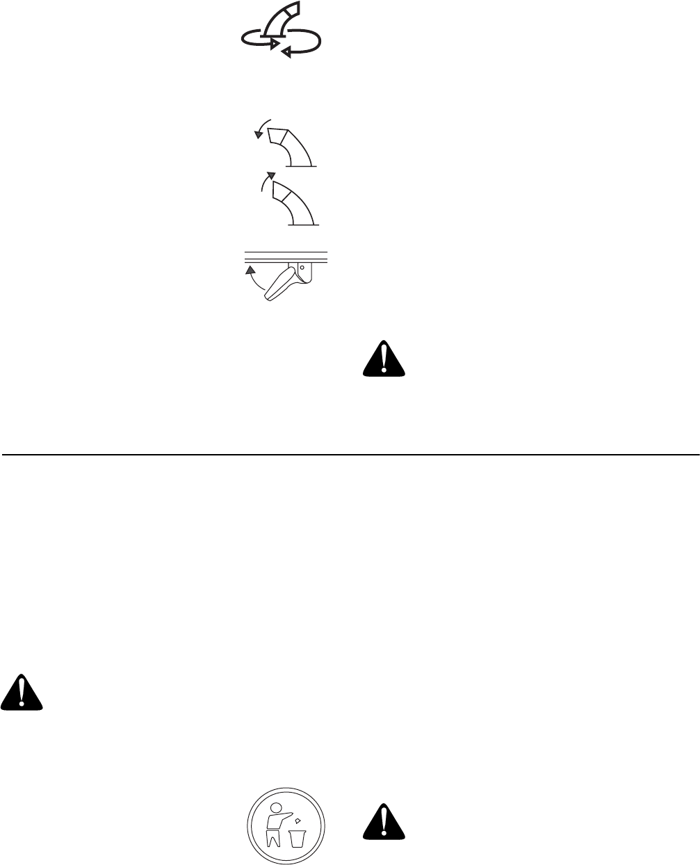
Chute Crank
The chute crank is located on the left
side of the snow thrower. Use it to
change the direction in which snow is
thrown. Avoid targetting persons,
animals or cars and buildings.
Chute Tilt Control
The distance snow is thrown can be
changed by adjusting the angle of the
chute assembly. Move the chute tilt
control forward to decrease the
distance, toward the rear to increase.
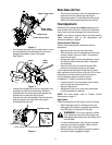
Wheel Steering Controls
The left and right wheel steering
controls are located on the underside
of the handles. See .
• Squeeze the right control to turn right; squeeze the
left control to turn left.
NOTE: Operate the snow thrower in open areas until
you are familiar with these controls.
Skid Shoe
The skid shoe position is determined by the condition of
the ground from where snow has to be removed. Higher
the snow level, lower will be the skid shoe. Adjust it
accordingly.
Headlight
The headlight is on whenever the engine is running.
Throttle Control
The throttle control is located on the engine. It regulates
the speed of the engine.
Safety Ignition Key
The safety ignition key must be fully inserted in the
switch before the unit will start. Remove key when snow
thrower is not in use. Do not attempt to turn the key.
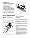
Chute Clean-Out Tool
The chute clean-out tool is designed to clear a clogged
discharge chute. Refer to page 11 for instructions on
how to properly use it.
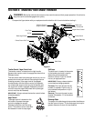
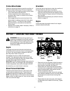
SECTION 4: OPERATING YOUR SNOW THROWER
Before Starting
Read and understand all instructions and warnings on
the machine and in this manual before operating.
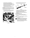
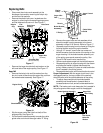
Gas & Oil Fill-Up
• Service the engine with gasoline and oil as
instructed in the engine manual shipped with the
snow thrower.
• A plastic cap is provided inside
the fuel fill opening on the fuel
tank. Remove and discard this
cap before filling up the tank. Use
the proper fuel tank cap to close
after fill-up.
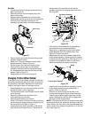
To Start Engine
NOTE: If unit shows any sign of motion (drive or
augers) with the clutch grips disengaged, shut engine
off immediately. Readjust as instructed in the Final
Adjustments in the Assembly Section.
• Attach spark plug wire to spark plug.
• Make certain the auger and drive clutch levers are
in the disengaged (released) position.
• Move throttle control up to FAST position.
• Insert ignition key into slot. Be certain it snaps into
place. Do not turn key.
NOTE: Engine will not start unless ignition key is
inserted into ignition slot in carburetor cover.
Electric Starter
CLOCKWISE TO
DISCHARGE LEFT
COUNTER CLOCKWISE
TO DISCHARGE RIGH
T
WARNING: Never use your hand to clear a
clogged discharge chute. Shut off engine and
remain behind handles until all moving parts
have stopped before unclogging.
WARNING: Use extreme care when
handling gasoline. Gasoline is extremely
flammable and the vapors are explosive. Never
fuel machine indoors or while the engine is hot
or running. Extinguish cigarettes, cigars, pipes
an other sources of ignition.
WARNING: The electric starter is equipped
with a grounded three-wire power cord and
plug and is designed to operate on 120 volt AC
household current. It must be used with a
properly grounded three-prong receptacle at all
times to avoid the possibility of electric shock.
Follow all instructions carefully prior to
operating the electric starter.