


12
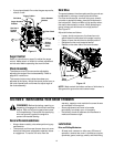
• If you placed plastic film under the gas cap earlier,
remove it now.
Figure 11
Auger Control
Refer to instructions on page 6 to adjust the auger
control. Make certain to check for correct adjustment
as instructed before operating the snow thrower.
Chute Assembly
The distance snow is thrown can be adjusted by
adjusting the angle of the chute assembly. Refer to
page 8 for instructions.
The remote chute control cables have been pre-
adjusted at the factory. Move the remote chute lever on
the control panel back and forward to adjust angle of
the chute assembly.
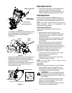
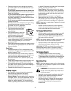
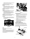
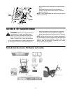
Skid Shoe
The space between the shave plate and the ground can
be adjusted by raising or lowering the skid shoes.
For close snow removal, as when using on a smooth
concrete or asphalt driveway, place the skid shoes in
the low position. Use the middle or high position when
the area to be cleared is uneven. When operating on
gravel, always put skid shoes in the high position.
See Figure 12.
Adjust skid shoes as follows:
• Loosen, but do not remove, the three hex nuts
which fasten the skid shoe to the auger housing.
• Raise or lower the skid shoe to desired position.
• Retighten the hex nuts loosened earlier.
• Repeat on the other side of the snow thrower.
Figure 12
NOTE: Make certain the bottom surface of skid shoe is
flat against the ground to avoid uneven wear
SECTION 6: MAINTAINING YOUR SNOW THROWER
General Recommendations
• Always observe safety rules when performing any
maintenance.
• The warranty on this snow thrower does not cover
items that have been subjected to operator abuse
or negligence. To receive full value from the
warranty, operator must maintain the snow thrower
as instructed in this manual.
• Some adjustments will have to be made
periodically to maintain your unit properly.
• Periodically check all fasteners and hardware to
make sure these are tight.
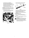
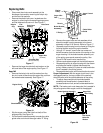
Lubrication
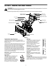
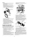
Drive and Shifting Mechanism
• At least once a season or after every 25 hours of
operation, remove rear cover. Lubricate any chains,
sprockets, gears, bearings, shafts, and the shifting
Trigger Cables
Shift Arm
Drive Actuator
Auger Actuator
Hex Nut &
Hex Gear Shaft
Drive Plate
Rubber
Bracket
Bracket
Cupped
Washer
Friction
Wheel
High
Hex Nuts
Carriage Bolts
Skid
Low
Shave Plate
Shoes
WARNING: Before lubricating, repairing, or
inspecting, disengage all clutch levers and stop
engine. Wait until all moving parts have come
to a complete stop. Disconnect the spark plug
wire and ground it against the engine to
prevent unintended starting.