


MAINTENANCE INSTRUCTIONS
SERVICING THE UNIT
Extreme care and knowledge of the system is required
when servicing this unit. Service should be performed by
qualified ser
vice personnel only. Replacement parts for this
unit must be identical to the parts they replace. Refer any
repair to an author
ized service dealer.
INSPECTING/REPLACING THE DRIVE BELT
When servicing the unit, use only original equipment man-
ufacturer replacement parts. Inspect the drive belt once a
year or every 50 hours of operation, whichever comes first,
for wear. If the drive belt needs to be replaced, use the fol-
lowing instructions.
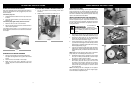
1. Remove the 7 screws (A) from the belt case cover (B)
using a #T20 torx bit or flat blade screwdriver. (Fig. 7)
2. Remove the flange lock nut (C) and remove the 3
screws (D) from the belt case cover (E) using a #T20
Torx bit or flat blade screwdriver. (Fig. 8)
3. Pull the belt tensioner (F) away from the drive pulley
(G). Remove the damaged or broken belt (H) from the
driven pulley (I) and drive pulley inside of the housing.
Discard appropriately. (Fig. 9)
4. Loop the new belt around the drive pulley and driven
pulley (Fig. 8). Pull the belt tensioner (idler arm) away
from the drive pulley to install the belt around the drive
pulley.
NOTE: Make sure the washer is still in place on the driven
pulley shaft prior to reinstalling the belt case cover.
5. Reinstall the flange lock nut. Torque the nut to 50-100
in• lb (90-11.2 N•m) and reinstall the 3 screws. Torque
all screws to 18-23 in• lb (20-2.5 N•m).
6. Reinstall the cover with the 7 screws. To make instal-
lation easier, place the narrow part of the cover into
the recess of the housing. Install the top 2 screws,
then push the rest of the cover down into the recess
and over the rotor shaft. Toque all 7 screws to 18-23
in• lb (20-2.5 N•m)
NOTE: If the flange lock nut is damaged, do not replace it
with a standard nut. Replace only with an original equip-
ment manufacturer replacement part.
To avoid serious
personal injury,
turn off the unit and allow it to cool. Unplug
the unit before you perform any mainte-
nance.
WARNING:
Fig. 7
A x 7
Fig. 8
C
D
E
B
Fig. 9
F
G
H
I
10
OPERATING INSTRUCTIONS
OVERLOAD PROTECTION SWITCH
This unit is equipped with an overload protection switch to
protect the circuit (that the unit is plugged into) from short
circuit overloads.
If the switch pops out:
1. Release the bail and allow the unit to stop and cool for
a minute.
2. Press the overload switch (A) to reset. Resume oper-
ation. (Fig. 5)
If the switch pops again shortly after the first time:
1. Allow the unti to cool for 15 to 30 minutes.
2. After the unit has cooled, press the overload switch to
reset. Resume operation.
If the s
witch does not stay in or if it continues to pop out
dur
ing operation, take the unit to an autorized service deal-
er for repair.
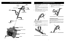
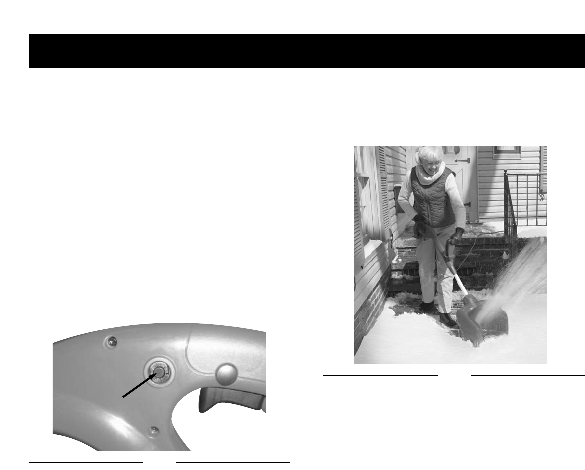
OPERATING THE SNOW THROWER
1.
Star
t the unit according to the star
ting instructions.
The depth and w
eight of the sno
w go
v
er
ns the forward
speed.
2. Push the unit so that it rides on the scraper.
3. Make sure the power cord is attached to the cord
retainer. The power cord should trail to the side of the
operator.
TIPS FOR BEST SNOW THROWING RESULTS
1. For the most efficient snow throwing, throw snow
downwind.
2. Slightly overlap each swath you make. (Fig. 6)
Fig. 5
A
Fig. 6
9