


8
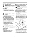
Now move the shift lever to FORWARD (Wheels
Forward) position. Carefully engage the clutch by lifting
the clutch control bail against the handle. The wheels
should spin.
If the wheels do not spin with the unit in forward,
adjust by unthreading the tube at the end of the cable a
few turns counter-clockwise, (when standing in
operator’s position), and then retighten the nut against
the tube.
Recheck both adjustments, and readjust as necessary.
NOTE: A secondary cable adjustment is available if
you reach the point that additional adjustment is
needed. Remove the belt cover and move the hex nuts
at the other end of the cable towards the end of the
casing. Then readjust the hex nuts at the handle.
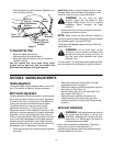
Tire Pressure
The tires on your unit may be over-inflated for shipping
purposes. Reduce the tire pressure before operating
the unit. Recommended operating tire pressure is
approximately 20 p.s.i. (check sidewall of tire for tire
manufacturer’s recommended pressure).
WARNING: Maximum tire pressure under
any circumstances is 30 p.s.i. Equal tire
pressure should be maintained on both tires.
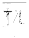
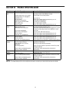
SECTION 4: KNOW YOUR TILLER
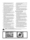
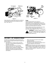
Figure 6
Throttle Control
The throttle control lever is located on the engine. It
controls the engine speed and stops the engine. See
Engine manual for further information.
Control Lever
The choke lever is located to the left of the throttle. It is
used to enrich the fuel mixture in the carburetor when
starting a cold engine. See Engine manual for further
information.
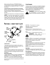
Gear Selection Handle
The gear selection handle is located in the center of the
handle on the tiller. It is used to select NEUTRAL,
REVERSE, or one of the FORWARD modes (see
below). Pull or push the handle so that the indicator on
top of shift cover points to the operating mode desired.
See Figure 6.
NEUTRAL—Transmission is in neutral.
REVERSE—Reverse wheel drive.
FORWARD Modes:
Wheels Forward— Forward wheel drive only.
Tines Reverse— Forward wheel drive and reverse tine
drive.
Tines Forward— Forward wheel and tine drive.
WARNING: Make certain unit is in
NEUTRAL when starting the engine.
NOTE: If difficulty is encountered in moving the gear
selection handle, move the tiller forward or backward
slightly to allow the gears to synchronize.
Clutch Control Bail
The clutch control bail is located below the handle. See
Figure 6. Lifting the clutch control bail against the
handle engages the wheel and tine drive mechanisms.
NOTE: Never engage clutch lever while shifting.
Depth Stake
The depth bar controls the tilling depth. Refer to
SECTION 5: OPERATING YOUR TILLER on this page.
Handle Adjustment
The handle may be adjusted to be raised or lowered in
line with the tiller. To adjust the handle position loosen
the handle height adjustment crank a few turns. Pivot
handle up or down to desired position. Tighten crank.
Height
Adjustment
Lever
Control
Rod
Gear
Selection
Handle
Clutch
Control
Bail
Clutch
Cable
Cable Tie