


6
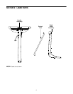
SECTION 3: ASSEMBLING YOUR TILLER
IMPORTANT:
This unit is shipped WITHOUT GASOLINE
or OIL. After assembly, see separate engine manual for
proper fuel and engine oil recommendations.
NOTE: Left and right is determined from the
operator’s position, standing behind the tiller.
Tools Required For Assembly
• Adjustable Wrenches
• Pair of Pliers
• Screw Driver
To Remove Unit From Carton
• Remove staples, break glue on top flaps, or cut
tape at carton end and peel along top flap to open
carton.
• Remove loose parts included with unit (i.e.,
operator’s manual, etc.).
• Cut corners and lay carton down flat.
• Remove packing material.
• Roll or slide unit out of carton. Check carton
thoroughly for loose parts.
• Extend control cable and lay on the floor. Be careful
not to bend or kink control cable.
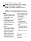
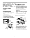
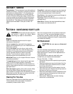
Figure 1
Attaching Depth Stake Assembly
• Tip the tiller forward so it rests on front
counterweight.
• Raise the tine shield hinge flap assembly. Remove
"T" knob, flat washer and hex bolt from depth stake.
Insert the depth stake assembly in front of spacer
(under the tine shield) and up through the tine
shield assembly as shown in Figure 1.
• Insert clevis pin through the tine shield and the
second hole from top of the depth stake. Secure
with hairpin clip.
• Insert hex bolt into the top hole of the depth stake
assembly. Place flat washer on hex bolt and thread
“T” knob onto the hex bolt. See Figure 1. Tighten
securely.
• Tip the tiller back down so it rests on the depth
stake (transport position).
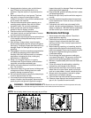
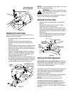
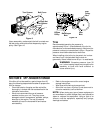
Attaching The Handle Assembly
Figure 2
• Remove top two bolts and flange lock nuts from
handle mounting brackets as shown in Figure 2. Do
not remove the bottom bolt and nut.
• Place handle assembly in position between the
handle mounting brackets. See Figure 2.
• Line up holes in handle with holes in handle
mounting brackets. Secure with hardware removed
in step 1.
T-Knob Hex Bolt
Washer
Depth
StakeStake
T-Knob
Hex Bolt
Washer
Clevis Pin
Hairpin Clip
Depth Stake
Remove
Handle
Ass’y
Handle
Bracket