


14
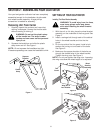
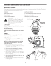
7. Replace the air filter inside the air filter/muffler
cover. See Figure 24.
NOTE: Operating the unit without the air filter and air
filter/muffler cover assembly, will VOID the warranty.
8. Place the air filter/muffler cover over the back of
the carburetor and muffler.
NOTE: The choke control must be in the PARTIAL
choke position (B) to install the air filter/muffler cover.
See Figure 23.
9. Insert the four (4) screws into the holes in the air
filter/muffler cover and tighten. See Figure 23.
Use a flat blade or # T20 Torx bit screwdriver. Do
not over tighten. Do not force.
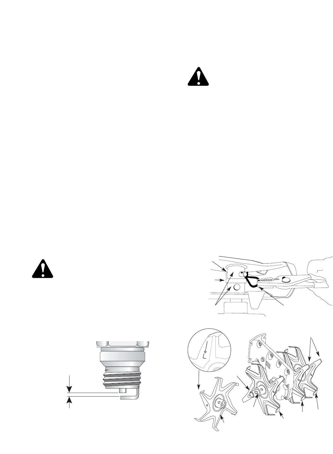
Figure 26
Figure 27
Figure 28
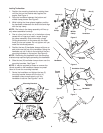
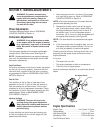
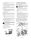
Replacing The Spark Plug
Use a Champion RDJ7Y spark plug (or equivalent).
The correct air gap is 0.020 inch (0.5 mm). Remove
the plug after every 50 hours of operation to check its
condition.
1. Stop the engine and allow it to cool. Grasp the
plug wire firmly and pull the cap from the spark
plug.
2. Clean dirt from around the spark plug. Remove
the spark plug from the cylinder head by turning a
5/8 in. socket counterclockwise.
NOTE: Replace cracked, fouled or dirty spark plug.
3. Set the air gap at 0.020 inch (0.5 mm) using a
feeler gauge. See Figure 26.
CAUTION: Do not sand blast, scrape, or
clean electrodes. Grit in the engine could
damage the cylinder.
4. Install a correctly gapped spark plug in the cylin-
der head. Tighten by turning the 5/8 inch socket
clockwise until snug.
If using a torque wrench torque to;
110-120 in.•lb. (12.3-13.5 N•m).
Do not over tighten.
0.020 inch
(0.5 mm)
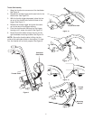
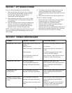
Clevis Pin Clip
Felt
Cushion
Shaft
Felt
Cushion
Tine Hubs
Align Tips
R
R
L
L
Clevis Pin
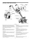
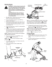
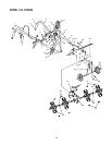
Tine Removal And Replacement
All 4 tines should be replaced at the same time
because they will wear evenly through normal use.
Work on one side at a time.
WARNING: To prevent serious personal
injury, always wear heavy gloves when
handling the tines.
1. Put the On/Off Stop Control in the STOP (O)
position and disconnect the spark plug wire.
2. Remove the clevis pin clips and clevis pins. See
Figure 27.
3. Remove the tines and felt cushions from the
shaft.
4. Clean and oil the shaft.
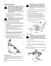
5. The tines are stamped with the letter "R" or "L" to
identified their position on each side of the gear-
box when facing the front of the unit.
6. Replace the tines and felt cushions onto the shaft
with the hubs on the tines facing each other.
7. Ensure the tips on tines are aligned in the same
direction with each other before reinstalling the
clevis pins and pin clips. See Figure 28.
8. Repeat this procedure on the opposite side.
NOTE: When installed correctly, there will be an "R"
and "L" tine on each side of the gearbox and the
tips on the tines line up in the same direction. It is
important that the tines are installed correctly.