


7
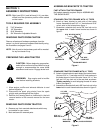
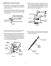
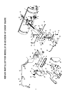
21.Insert the end of the lower lift handle assembly through
the notch in the pivot support bracket and through the
holes in the channel. Align the lift link pin with the hole
in the welded bracket on the lower lift handle assem-
bly. Insert the lift link pin through the hole in the
bracket and secure it with a 3/32" hair cotter pin. See
figure 11.
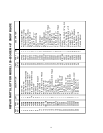
22.Assemble the handle grip onto the upper lift handle.
See figure 12.
23.Place the upper lift handle onto the lower lift handle
assembly. Align the holes and secure with the clevis
pin and a 3/32" hair cotter pin. See figure 12.
LOWER LIFT
HANDLE ASSEMBLY
WELDED
BRACKET
LIFT
LINK
PIN
3/32" HAIR
COTTER PIN
CHANNEL
Figure 11
Figure 12
CLEVIS PIN
UPPER LIFT HANDLE
LOWER LIFT HANDLE
ASSEMBLY
3/32" HAIR
COTTER PIN
HANDLE GRIP
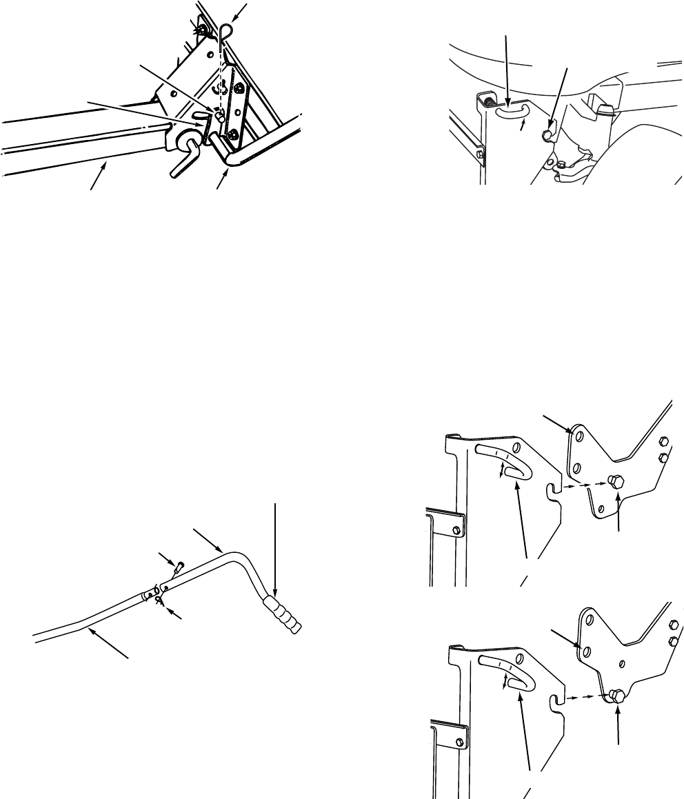
SHOULDER BOLT
ATTACHMENT PIN
PIN IN THIS HOLE
FOR 15" TIRES
Figure 14
SHOULDER BOLT
ATTACHMENT PIN
PIN IN THIS HOLE
FOR 16" TIRES
SHOULDER BOLT
ATTACHMENT PIN
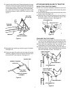
STANDARD TRACTOR FRAMES
27.To attach the hitch assembly to the front of the tractor,
pull out on the attachment pins and swing the pins
down away from the holes they were in. See figure 14.
28.Hook the hitch assembly onto the shoulder bolts
assembled to the frame brackets. See figure 14.
29.Align the holes in the hitch assembly with the holes in
the frame brackets. Insert the attachment pins to lock
the hitch assembly in place. See figure 14.
Figure 13
ATTACHING SNOW BLADE TO TRACTOR
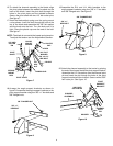
QUICK ATTACH TRACTOR FRAMES
24.Pull out on the hitch assembly's attachment pins and
swing the pins down away from the holes they were
in. See figure 13.
25.Hook the hitch assembly onto the shoulder bolts in the
tractor frame. See figure 13.
26.Align the holes in the hitch assembly with the holes in
the tractor frame. Insert the attachment pins to lock
the hitch assembly in place. See figure 13.