


4
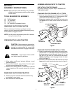
PREPARING THE LAWN TRACTOR
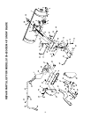
Figure 1
CAUTION: Before beginning preparation,
select a firm and level surface which is large
enough to accommodate the snow blade
attachment and tractor. Engage brake lock.
1. Allow engine, muffler and exhaust deflector to cool
before beginning.
2. Disconnect the spark plug wire(s) from the spark
plug(s) and ground against the engine.
3. Remove the mowing deck as instructed in the belt
removal section of the owner's manual for the lawn
tractor.
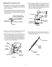
5/16" x 1"
HEX BOLTS
5/16" NYLOCK NUTS
SHOULDER BOLT
3/8" HEX
LOCK NUT
STANDARD TRACTOR FRAMES WITH 15" TIRES
6. Attach a frame bracket to each side of the tractor
frame. Assemble three 5/16" x 1" hex bolts and 5/16"
nylock nuts to the holes shown figure 1.
7. Assemble a shoulder bolt and a 3/8" hex lock nut to
the upper hole in each frame bracket as shown in
figure 1.
TOOLS REQUIRED FOR ASSEMBLY
(2) 7/16" Wrenches
(2) 1/2" Wrenches
(2) 9/16" Wrenches
(1) 3/4" Wrench or Adjustable Wrench
WARNING: Stop engine and let muffler
cool before installing brackets.
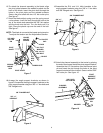
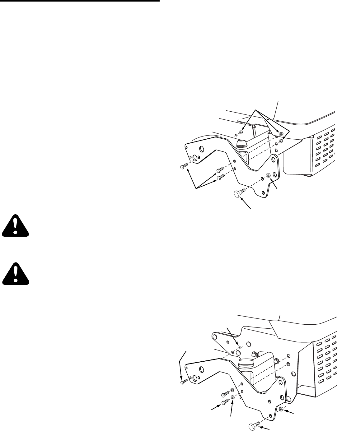
STANDARD TRACTOR FRAMES WITH 16" TIRES
8. Attach a frame bracket to each side of the tractor frame.
Use two 5/16" x 1" hex bolts and 5/16" lock washers in
the holes shown in front of the axle. Use a 1/4" x 1" hex
bolt and 1/4" hex lock nut in the rear hole as shown.
Tighten carefully to avoid stripping threads in tractor
frame. See figure 2.
9. Assemble a shoulder bolt and a 3/8" hex lock nut to the
lower hole in each frame bracket as shown in figure 2.
Figure 2
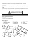
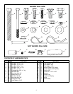
REMOVING PARTS FROM CARTON
Remove all parts and hardware packages from the
carton. Lay out all parts and hardware and identify using
the illustrations on pages 2 and 3.
NOTE: Not all parts in the hardware pack will be needed
for any one tractor fit-up.
ASSEMBLING BRACKETS TO TRACTOR
FAST-ATTACH TRACTOR FRAMES
No bracket assembly required. Skip to ASSEMBLING
THE SNOW BLADE.
REMOVING PARTS FROM TRACTOR
4. Remove any front mounted attachments which may
be installed on your tractor.
5. Mark and save all removed parts.
NOTE: Right hand (R.H.) and left hand (L.H.) are deter-
mined from the operators position while seated
on the tractor.
SECTION 1:
ASSEMBLY INSTRUCTIONS
5/16" x 1"
HEX BOLTS
5/16" LOCK
WASHERS
1/4" x 1"
HEX BOLT
1/4" HEX
LOCK NUT
SHOULDER BOLT
3/8" HEX
LOCK NUT