


5
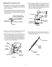
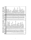
Figure 5
3/8" PALNUT
PIVOT
PLATE
SPRING
MOUNT
ROD
3/8" PALNUT
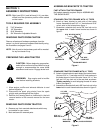
14.Using a hammer, assemble a 3/8" palnut onto one
end of the spring mount rod. Insert the other end of
the rod through the rear set of holes in the pivot
plate. Turn the pivot plate onto it's side on a block of
wood and hammer the remaining palnut onto the
other end of the rod. See figure 5.
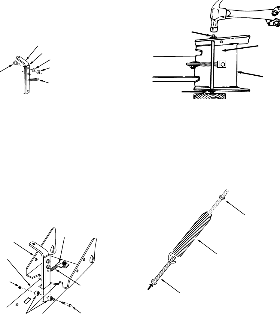
15.Insert the 3/8" x 3-1/2" hex bolt through the angle lock
spring. Assemble a 3/8" hex nut about 1" onto the end
of the bolt. See figure 6.
Figure 6
3/8" x 3-1/2"
HEX BOLT
BLADE
ADJUST
SPRING
3/8" HEX NUT
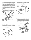
Figure 4
Figure 3
3/8" x 1"
CARRIAGE BOLT
3/8" LOCK WASHER
3/8" HEX LOCK NUT
ANGLE LOCK BAR (SHORT)
ANGLE LOCK BAR (LONG)
ANGLE LOCK SPRING
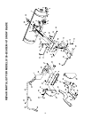
10.Assemble the long and short angle lock bars together
using two 3/8" x 1" carriage bolts, 3/8" lock washers
and 3/8" hex lock nuts. Make sure all holes are
aligned. See figure 3.
11.Insert the straight hook end the angle lock spring into
the middle hole in the angle lock bars. The curved
hook on the other end of the spring should be facing
up. See figure 3.
1/4" x 3-1/4"
HEX BOLT
1" SPACERS (2)
1/4" HEX
LOCK NUT
PIVOT
PLATE
ANGLE
LOCK
SPRING
BRACKET (A)
CHANNEL
12.Insert the curved hook of the angle lock spring up
through the hole in bracket (A). See figure 4.
13.Insert the angle lock bars down through the slot in the
channel. Underneath the channel place spacers on
both sides of the angle lock bars and insert a 1/4" x
3-1/4" hex bolt through the sides of the channel, the
spacers and the angle lock bars. Secure the bolt with
a 1/4" hex lock nut, tightening so that the angle lock
bars still pivot freely. See figure 4.
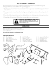
ASSEMBLING THE SNOW BLADE