


8
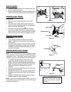
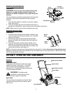
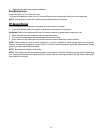
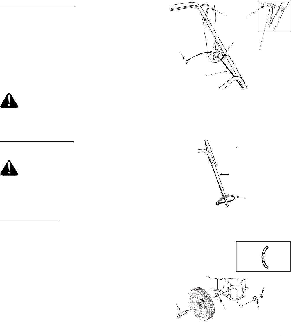
Attaching Brake Cable
1. Make certain the blade control handle is on the top of the
upper handle.
2. The brake cable is attached to the engine, and has a “Z”
fitting on the loose end. Route the brake cable over the
lower handle. Snap the plastic fitting into the hole on the
inside of the upper handle as shown in Figure 6.
3. Hook the “Z” end of the brake cable into the hole in the
blade control handle from the outside to the inside as
shown in Figure 6, inset.
4. Brake cable must be assembled as shown for proper
blade brake operaiton.
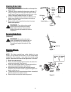
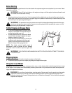
Securing Brake Cable
(Hardware F)
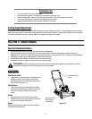
Attaching Wheels
(Hardware E)
NOTE: The holes provide three cutting heights for your
mower. Use the same hole location for all four wheels when
assembling. For example, if you desire the lowest cutting
position, assemble each wheel at the highest hole on the deck.
1. Block the mower securely.
2. Place axle bolt through the wheel with the hub side of the
wheel facing the deck. See Figure 8 .
3. Place the small cupped washer on the axle bolt with the
cupped side towards the deck. See Figure 8.
4. Secure the wheel to the deck with one larger cupped
washer on the inside of the deck (cupped side against the
deck) and the hex nut.
5. Tighten axle bolt until cupped washers flatten. Assembled
the other wheels in the same manner.
6. Remove blocks and put the mower on ground.
WARNING: The cable must be routed
properly to avoid contact with all sharp
edges and hot surfaces. Such contacts
damage the cable and render the controls
inoperative.
WARNING: Secure the cable to the
lower left handle near the base of the unit
with a cable tie from the hardware pack.
Trim off extra length of the cable tie. See
Figure 7.
Brake Cable
“Z” Fitting
Blade
Control
Handle
Snap
Fitting
Figure 6
“Z” Fitting
Figure 7
Lower
Cable Tie
Handle
Crowned
Cupped
Side
Side
Axle
Bolt
Larger
Cupped
Washer
Smaller
Cupped
Washer
Hex Nut
Figure 8