


7
Spark Plug Wire
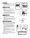
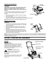
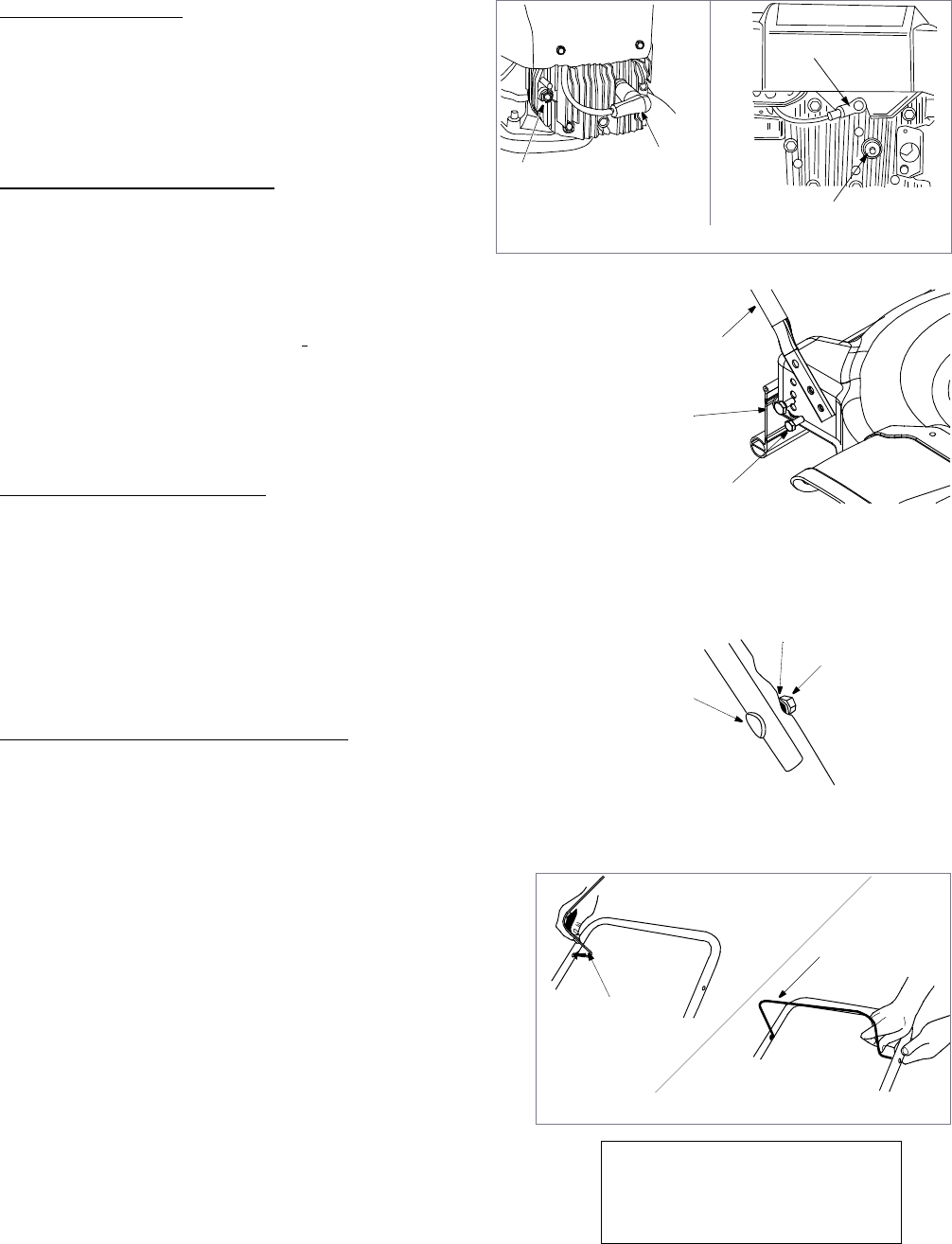
1. Disconnect spark plug wire from the spark plug, and
ground it against the engine.
2. If engine is equipped with a rubber boot, attach rubber
boot to a bolt on the engine to ground. See Figure 2.
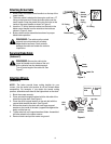
Attaching Lower Handle
(Hardware A)
1. Raise the rear of the deck and place it on a block
securely.
2. Place the lower handle over the deck aligning the
lower two holes in the handle with the corresponding
holes on the deck. See Figure 2.
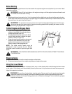
3. Attach the lower handle to the deck with shoulder
screws in the upper hole and hex screws in the lower
hole as shown in Figure 3, secure both with hex flange
locknuts. Using two 1/2” wrenches, tighten securely.
Attaching Upper Handle
(Hardware B)
1. Place the upper handle in position over the lower
handle. The blade control must be on the upper side
of the handle.
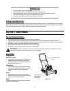
2. Secure the upper handle to the lower handle using the
carriage bolts, lockwashers and hex nuts, see Figure
4. Make sure that the carriage bolt heads go on the
outside of the handle.
Attaching Blade Control Handle
NOTE: If the blade control handle got displaced either
during shipping or during assembly of other two handles,
reassemble it now. If the blade control handle is firmly
secured in place, you may proceed to the next assembly.
1. To reattach the blade control handle to the upper
handle, first identify the proper holes in the upper
handle. This can be done by placing the blade control
handle flat against the upper handle. The ends of the
blade control handle will approximate the hole
positions.
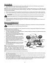
2. Insert the curved end of the blade control handle into
the right hole. See Figure 5.
3. Squeeze the handle in, and insert the straight end of
the blade control handle into the left hole of the upper
handle.
4. Squeeze the blade control handle against the upper
handle to check for proper assembly.
NOTE: The hole in the blade control handle must be on
the left side and the control handle must touch the upper
handle when squeezed.
Spark
Plug
Bolt
Spark Plug
Spark Plug
Wire
Wire
Figure 2
Lower Handle
Shoulder Screw
Hex Screw
Figure 3
Figure 4
Lockwasher
Hex Nut
Carriage Bolt
Blade Control
Handle
Insert curved end
Figure 5
IMPORTANT
The blade control handle is a safety
device. Never attempt to bypass its
operations.
of control handle
here.