


Model V-Max —19—
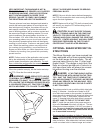
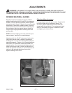
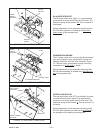
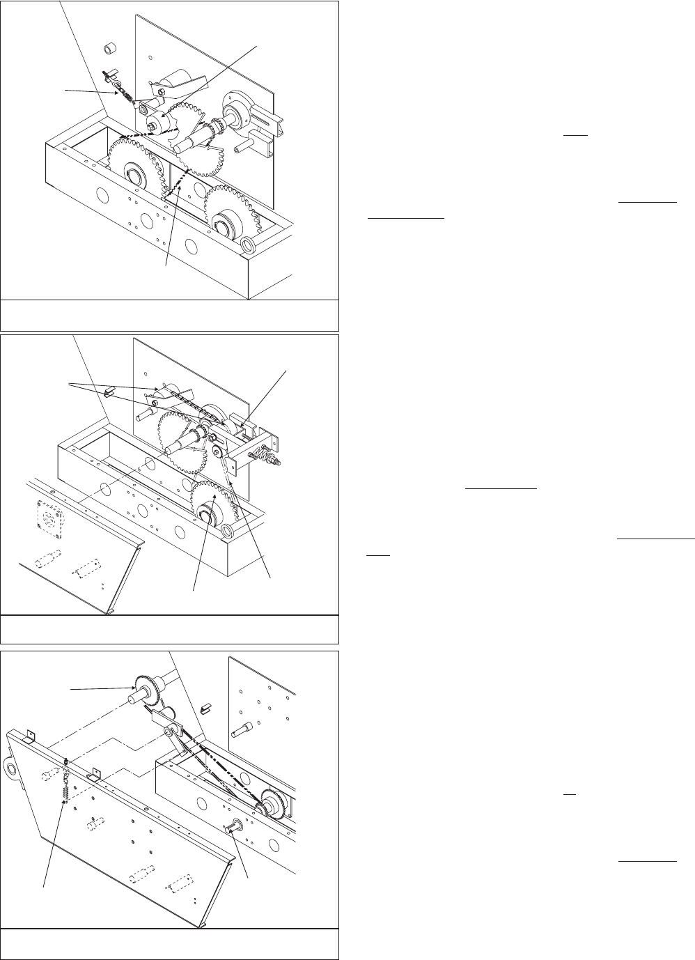
FIGURE 11. RH AUGER CHAIN DRIVE
SPRING
LOADED
ADJUSTER
IDLER
NYLON
ROLLER
ROLLER
CHAIN
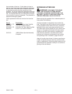
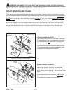
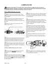
FIGURE 12. LH AUGER CHAIN DRIVE
IDLER
NYLON
ROLLERS
TRACKING
YOKE
LH AUGER SPROCKET
ROLLER CHAIN
RH AUGER SPROCKET
The RH auger chain drive, figure 11, is automatically
tensioned by a spring loaded idler NYLON roller. The
extension spring should extend 3/4"
from its neutral 4"
total length.
Manual adjustment for the automatic tensioning idler,
NYLON roller assembly is located at the right front
lower corner of the spreader tank.
COMPRESSION SPRING
The LH auger chain drive is automatically tensioned
by a spring loaded heavy compression spring and
tracking yoke/idler, NYLON roller assembly, figure
12. The one heavy compression spring should be
compressed to 3-1/2" to 4"
in length.
Manual adjustment for the automatic tensioning idler,
NYLON roller assembly is located at the left front cor-
ner of the spreader tank.
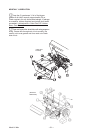
IDLER NYLON ROLLER
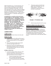
The side shaft chain drive (PTO input shaft to the side
line shaft drive sprocket, figure 13) is automatically
tensioned by a spring loaded idler NYLON roller. The
extension spring should extend 2"
from its neutral 5" to
-
tal length.
Manual adjustment for the automatic tensioning idler,
NYLON roller assembly is located at the right front
of
the spreader’s front bearing mounting plate.
FIGURE 13. SIDE SHAFT CHAIN DRIVE
SIDE LINE
SHAFT DRIVE
SPROCKET
PTO INPUT
SPRING LOADED
ADJUSTER