


VERY IMPORTANT: THIS MACHINE IS NOT IN
-
TENDED TO BE A BALE GRINDER, HAY CHOPPER
OR BEDDING MACHINE. LONG HAY OR STRAW
MUST CONTAIN MANURE IN ORDER TO BE
SPREAD. FAILURE TO COMPLY MAY DAMAGE
THE DRIVETRAIN AND VOID THE WARRANTY.
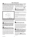
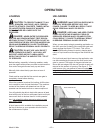
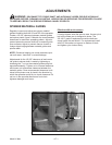
The rear spinners have been designed and tested to
provide the best spread pattern for most liquids and
semi solid manure. However, the pattern will vary for
each specific condition. The factors that contribute
most to differing patterns will be moisture content and
the amount and length of bedding material. For most
typical conditions, the spread pattern should be uni
-
form and about 15 ft. wide. When this is the case, plan
your spreading patterns so you do not have to travel
over previously spread manure which will be slippery,
resulting in poor traction. Traction on wet grass is also
poor. When the resulting pattern may require that
you overlap during spreading, use precautions on
slopes and hills where you could experience a loss
of traction by traveling over ground with previously
spread manure.
NOTE: Further control of the application rate is possi-
ble by the relationship of tractor engine speed to
ground speed (transmission gear selection). For opti-
mum, trouble-free performance it is necessary to oper-
ate at or near engine PTO speed.
When the spreader is empty, idle the tractor and stop
the PTO. Close the flow control rear gate.
WARNING: NEVER OPERATE PTO ABOVE
ITS NORMAL 540 RPM RATING. NEVER
CONNECT
SPREADER PTO SHAFT TO A 1000 RPM TRACTOR
PTO, UNLESS THE SPREADER IS EQUIPPED WITH
A 1000 RPM OPTIONAL KIT. TRACTOR PTO MUST
MATCH IMPLEMENT PTO. FAILURE TO HEED MAY
RESULT IN SPREADER DAMAGE OR SERIOUS
PERSONAL INJURY.
NOTE: Failure to idle the tractor before disengaging
the PTO will cause roller chain over-running and dam
-
age to the chain tighteners.
NOTE: Maximum life of the PTO shaft universal joints
will result if you stop the PTO while making turns at
the end of the field.
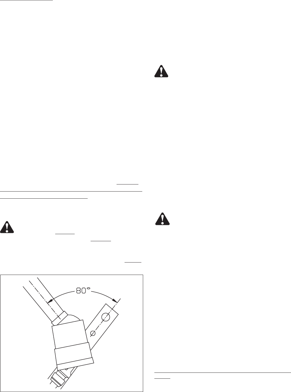
CAUTION: DO NOT EXCEED THE MAXI
-
MUM 80° TURNING ANGLE ON THE CONSTANT
VELOCITY PTO DRIVE LINE. EXCEEDING THE
TURNING ANGLE WILL DAMAGE THE CONSTANT
VELOCITY “CENTER HOUSING” AND WILL EXERT
EXCESSIVE PRESSURES ON THE PTO INPUT
CENTER SHAFT AND RELATED BEARINGS.
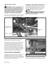
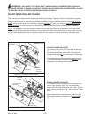
OPTIONAL SHEAR SPROCKET IN
-
STRUCTIONS
The Meyer Spreader you have received has
been equipped with a shear sprocket design
on the main auger drive sprockets. The au-
gers are being driven by two ½” allen head
grade 8 bolts. The design is such that if the
bolts are sheared another set of holes to in-
stall new shear bolts will always be accessi-
ble without turning over the machine.
DANGER:
AT NO TIME SHOULD INSTAL-
LATION BE DONE WITH ANYONE ON THE TRAC
-
TOR. SHUT THE TRACTOR OFF, REMOVE THE
KEY AND DISCONNECT THE DRIVE LINE BEFORE
DOING ANY SERVICE ON THIS MACHINE. SERI
-
OUS INJURY OR DEATH MAY OCCUR IF SAFETY
IS NOT FOLLOWED.
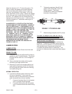
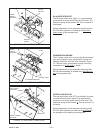
The plate sprocket is set up with the initial drive bolts
being ½” diameter. An extra set of holes for 9/16”
drive bolts are located on the sprocket if a additional
shear strength is needed due to shear bolt failure from
obstruction. If the ½” bolts shear, replace with the
same ½” diameter bolts after obstruction is removed.
DO NOT JUMP TO THE UP TO THE NEXT SIZE
BOLT. Install the new bolts in the proper way as to
drive off of the head of the bolt, not the nut. The two
different size holes available (½ & 9/16”) are close in
size. Be sure to install the proper size bolt into the
correct size hole. Shear or sprocket failure will oc
-
cur if assembled incorrectly!
Recommended procedure to follow if shear does
occur. If only one auger shears unload the opposite
side of spreader and remove obstruction from sheared
side of machine. After obstruction has been removed
install new shear bolts in sheared auger and unload
Model V-Max —13—