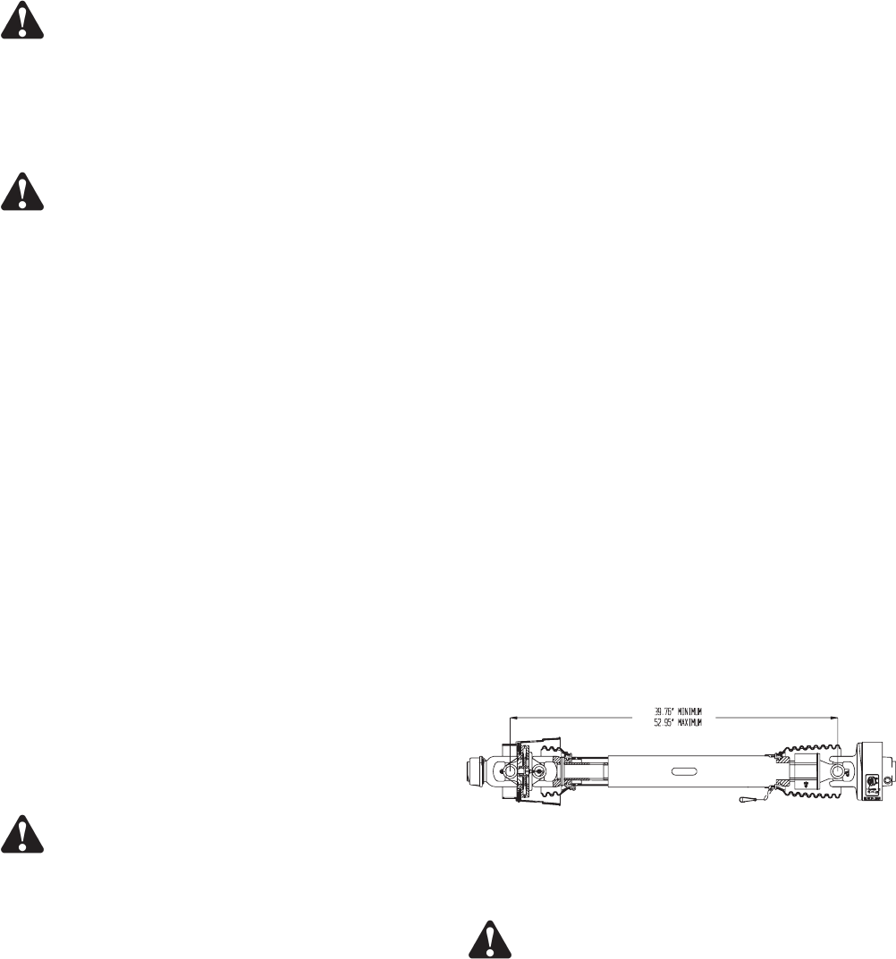
PTO DRIVE LINE
WARNING: BEFORE ATTEMPTING TO OP
-
ERATE THIS SPREADER, READ AND STUDY ALL
SAFETY INFORMATION. IN ADDITION, MAKE
SURE THAT EVERY INDIVIDUAL WHO OPERATES
OR WORKS WITH THE SPREADER, WHETHER
FAMILY MEMBER OR EMPLOYEE, IS FAMILIAR
WITH THESE SAFETY PRECAUTIONS.
WARNING: DISCONNECT PTO DRIVE
SHAFT AND HYDRAULIC HOSES (RELIEVE HY
-
DRAULIC PRESSURE) BEFORE CLEANING, AD
-
JUSTING, LUBRICATING OR SERVICING THIS
SPREADER. FAILURE TO HEED MAY RESULT IN
SERIOUS PERSONAL INJURY OR DEATH.
The Meyer V-Max Spreader is equipped with a cutout
type clutch on the implement half of the PTO drive line.
The clutch is designed to limit the amount of torque
transferred to the machine through the drive line. If
excessive torque is developed the clutch will disen
-
gage. A loud ratcheting sound will be heard and the
transfer of power to the machine will be disrupted. To
re-engage the machine simply shut down the PTO and
allow the drive line to come to a stop. The PTO can
then be re-engaged to restart the spreader. The cut-
out clutch will either re-engage upon shut down of the
PTO or just before it comes to a complete stop.
The cutout clutch will disengage if start up is done in
an abrupt or reckless manner. It also will disengage
from foreign materials entering the spinner area of the
spreader. It may also be possible to disengage the
clutch by overloading or flooding the spinners with free
flowing or liquid manure. If PTO clutch fails to re-en
-
gage it will be necessary to remove the foreign object
from the spreader before restarting. THERE IS NO
FIELD ADJUSTMENT ON THE CUTOUT CLUTCH.
DANGER: NEVER ENTER THE SPREADER
BOX FOR ANY REASON WITHOUT FIRST PER
-
FORMING THESE STEPS:
l
STOP THE TRACTOR, SHUT THE TRACTOR
OFF AND REMOVE THE KEY.
l
SET THE PARKING BRAKE AND DISCONNECT
THE PTO DRIVE LINE FROM THE TRACTOR.
l
DO NOT ALLOW OTHERS IN THE BOX.
ROTATING AUGERS CAN CRUSH AND DISMEM
-
BER. FAILURE TO HEED MAY RESULT IN SERI
-
OUS PERSONAL INJURY OR DEATH.
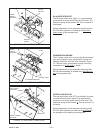
DRIVE LINE ATTACHMENT
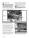
The cutout clutch end of the PTO drive line must al
-
ways be attached to the implement. The PTO drive
line is equipped with a 1 3/8-6 spline on the implement
half for attaching to the spreader. Remove the
M17-hexagon bolt from the splined hub and slide the
PTO onto the implement splined input shaft. Install the
hexagon bolt through the hub being sure the bolt is
falling into the groove on the splined shaft. Torque
tight using a metric size M17 6-point socket and torque
down to 75 ft. lbs. A M17 6-POINT METRIC SOCKET
MUST BE USED AS ROUNDING OF HEXAGON
BOLT AND INACCURACY OF TORQUE SETTINGS
COULD OCCUR.
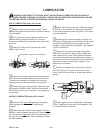
If removal of the M-17 hexagon bolt is necessary, use
the same M-17 6-point socket and loosen bolt 1/2
turn. Insert a ¼” drift punch in the hole on the opposite
side of the hexagon bolt and tap to loosen the seated
portion of the bolt from the splined hub. Repeat in 1/2
turn increments until loose. After bolt seat has been
released, remove the bolt. If bolt is not unseated, dam-
age to the hexagon bolt will occur.
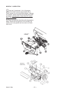
Attach the shield safety chain to a suitable area on the
spreader, preferably to the implement PTO steel
shield.
DANGER: NEVER ENTER THE SPREADER
BOX FOR ANY REASON WITHOUT FIRST PER
-
FORMING THESE STEPS:
l
STOP THE TRACTOR, SHUT THE TRACTOR
OFF AND REMOVE THE KEY.
l
SET THE PARKING BRAKE AND DISCONNECT
THE PTO DRIVE LINE FROM THE TRACTOR.
l
DO NOT ALLOW OTHERS IN THE BOX.
ROTATING AUGERS CAN CRUSH AND DISMEM
-
BER. FAILURE TO HEED MAY RESULT IN SERI
-
OUS PERSONAL INJURY OR DEATH.
Model V-Max —15—
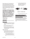
FIGURE 6. PTO DRIVE LINE


