


41
shipment of your telescope. It is only necessary for you to confirm that the telescope
has not been badly jarred out of collimation, and to perform the final fine-tuning of Step
4, below.
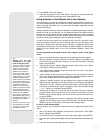
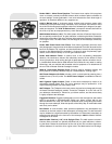
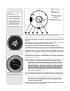
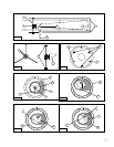
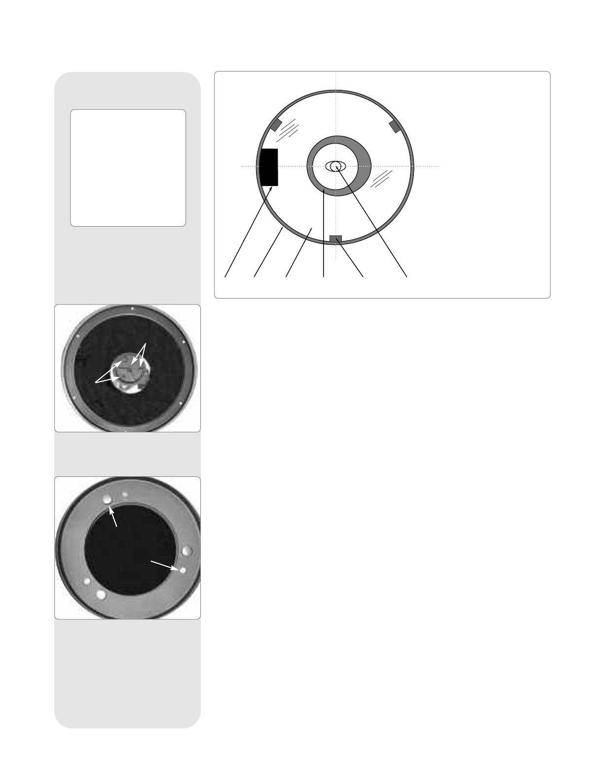
Fig. 31a shows a correctly collimated Schmidt-Newtonian telescope, as it appears
when viewed through the focuser with the eyepiece removed.
To check and, if necessary, set the optical collimation, follow these steps.
1. Observe through the focuser and orient your body so that the telescope's primary
mirror is to your right, and the correcting plate end of the telescope tube is to your left.
The diagonal mirror will appear centered as shown (
2, Fig. 31a). If the diagonal
appears off center, then adjust the 4 collimation screws on the plastic diagonal mirror
housing.
2.
If the reflection of the pr
imary mirror (
3,
Fig.
31a
) is not centered on the surf
ace of
the diagonal mirror
, adjust the 4 collimation scre
ws on the plastic diagonal mirror
housing to center the reflection.
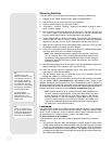
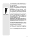
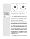
As described above, the 4 collimation screws (
Fig. 31b) on the plastic diagonal mirror
housing are used f
or tw
o diff
erent adjustments dur
ing the collimation procedure
.
Impor
tant Note:
Do not f
or
ce the 4 scre
ws past their normal travel, and
do not r
otate an
y scre
w or screws more than 2 full turns in a counter-
c
lockwise direction (i.e., not more than 2 full turns in their "loosening"
direction), or else the diagonal mirror may become loosened from its
support. Note that the diagonal mirror collimation adjustments are very
sensitive:
g
enerall
y turning a collimation screw 1/2-turn will have a dra-
matic eff
ect on collimation.
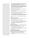
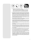
3. If the reflection of the diagonal mirror is not centered within the reflection of the pri-
mary mirror, adjust the 3 collimation screws located on the rear of the primary mirror
cell.
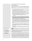
Note: There are 6 screws (Fig. 31c) on the primary mirror cell. The 3
kn
urled knobs are the collimation screws, and the 3 smaller thumb screws
are locking screws. The locking screws must be loosened slightly in order
to adjust the collimation screws.
Proceed by "trial and error" until you develop a feel for which collimation screw to turn
in order to change the image in any given way.
b F
ocuser drawtube
c Diagonal mirror
d Reflection of pr
imary
mirror
e Reflection of secondar
y
mirror (darkened due to
bac
k lighting)
f Pr
imary mirror clips
g Reflection of obser
ver's eye
b c d e f g
Fig. 31a: The view you will see while collimating a Schmidt-Newtonian telescope.
Tip:
A useful tool for making
collimation easier is to make
a hole in the plastic cap that
comes with the eyepiece to
protect it during shipping.
Use a drill to make a 1/8"
hole in the center of the cap
and place it over the eye-
piece holder for use during
the collimation procedure.
Fig. 31b: The four collimation screws
on the diagonal mirror housing.
Fig. 31c: The six collimation screws
on the
rear of the primary mirror cell.
knurled knob
thumb scre
w