


51
2. Loosen the R.A. Lock (33, Fig. 1d) and the Dec. Lock (17, Fig. 1d). Point the tube
so that it is above the tripod leg marked with a star. Retighten the Dec. Lock.
Move the counterweight shaft and mount so that it is parallel to the horizon. This
is position A. See Fig. 39. Retighten the R.A. Lock.
3. If using a Schmidt Newtonian model, rotate the optical tube (you will need to
loosen the cradle ring lock knobs (13, Fig. 1a) to do so) to make sure the focuser
extends horizontally from the optical tube while in position A and do not rotate the
tube for the remainder of the alignment procedure.
If using a refractor model, use the diagonal assembly to rotate the eyepiece
during testing. However, be careful that the diagonal is placed flush against the
focuser and tightened in place using the thumbscrews. It is important that the
diagonal does not slip during the procedure.
4. Adjust the tripod legs, polar axis altitude and/or polar axis azimuth so that the
wide, horizontal object you have chosen as a target is positioned across the mid-
dle of the eyepiece.
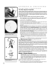
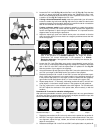
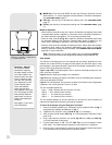
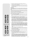
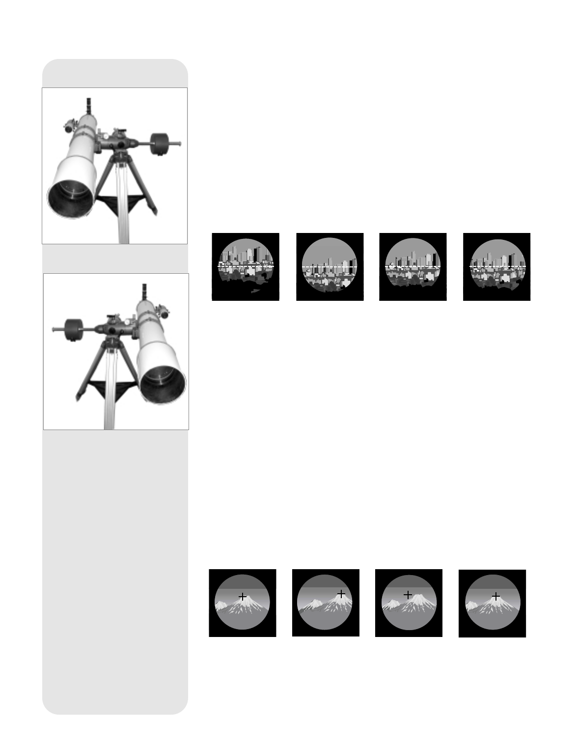
Procedure #1: Step 4 Step 5 Step 6 Step 7
Important Note: The image will appear right-side-up, but reversed left-for-
right, in the eyepiece of a refractor telescope. The image will appear
upside-down, but correct left-for-right, in the eyepiece of a Scmidt-
Newtonian telescope, if the eyepiece extends horizontally from the tube, as
described in Step #3.
5. Loosen the R.A. Lock (Tip: Make sure you do not accidentally loosen the Dec.
Lock. If you do, restart the procedure beginning at Step #2). Rotate the telescope
180° in the R.A. axis ONLY, until the optical tube is in position B. See Fig. 40.
Note the position of your target in the eyepiece.
6. Using the Autostar Up and Down Arrow keys ONLY, move the optical tube in Dec.
axis until your target is HALFWAY back to the center of the eyepiece.
7. Rotate the telescope 180° in the R.A. axis ONLY, to return the optical tube to posi-
tion A. Verify that your target is in the same location in the eyepiece vertically as
in the previous step (that is, it is not higher or lower or absent from the eyepiece).
Ignore side-to-side misalignment (that is, if it has moved to the right or left).
8. Repeat steps 6 and 7, if necessary, alternating positions A and B, until the hori-
zontal object is in the same vertical location in the eyepiece in both positions.
9. The Dec. optical axis is now calibrated to be at 90 degrees. For Procedure #2,
DO NOT adjust the declination of the optical tube, either manually or with the
handbox.
Procedure #2:To correct for elevation misalignment
After performing the attitude correction, select an object that is at a very great distance
(at least a mile away) to approximate infinity. Ideally, the object should be unique, with
several identifiable objects to the left and right of it.
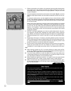
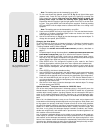
Procedure #2: Step 2 Step 4 Step 5 Step 6
1. Rotate the mount about the R.A. axis only and move the optical tube to position A.
2. WITHOUT moving the declination axis from its position determined in the previ-
ous alignment, adjust the legs, latitude, and azimuth of the tripod to center the
object in the eyepiece.
3. Rotate the telescope 180° in the R.A. axis ONLY, until optical tube is in position B.
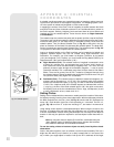
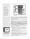
Fig. 40: Position B.
Fig. 39: Position A.