


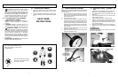
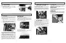
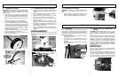
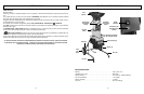
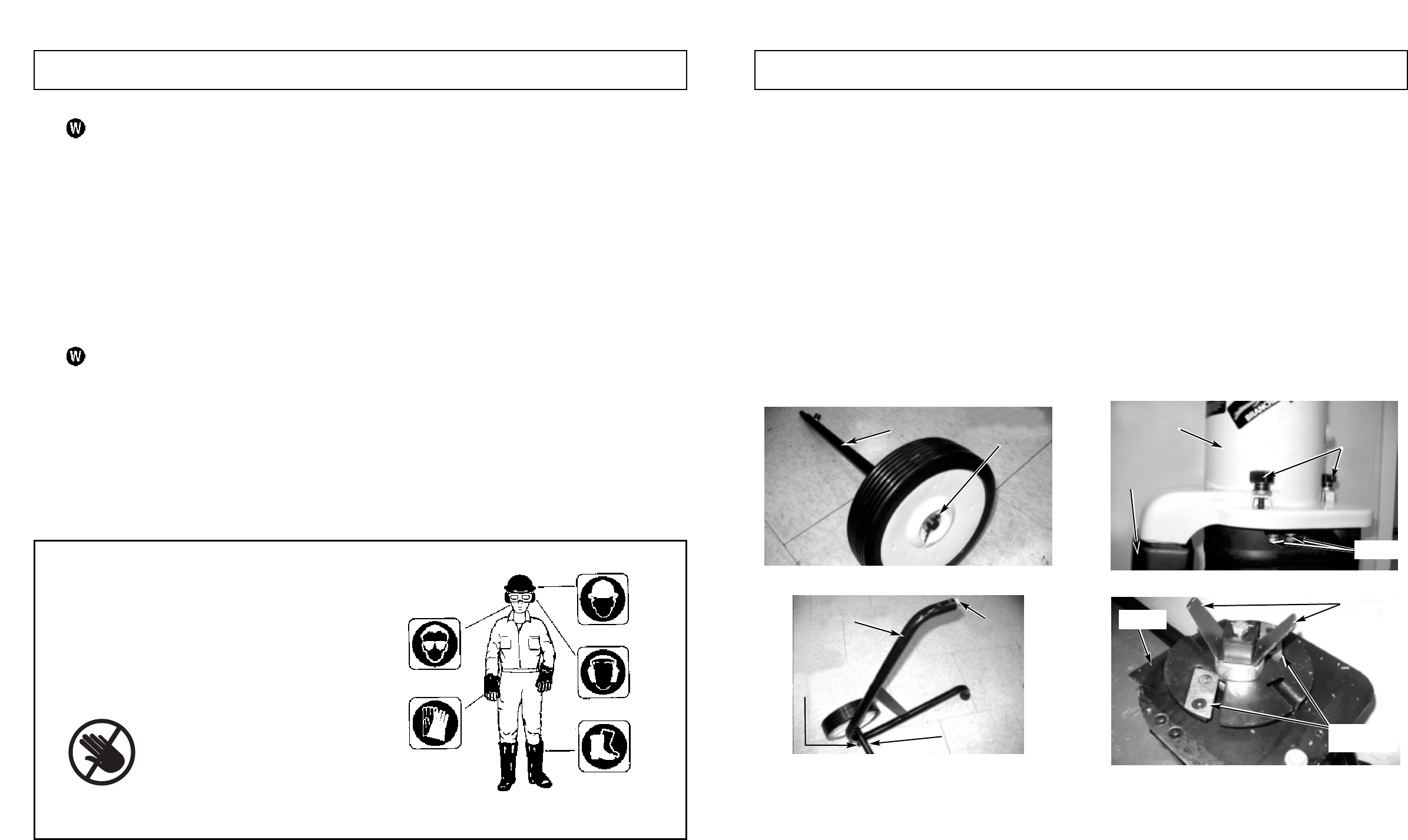
3-1. CONNECTING WHEEL ASSEMBLY
NOTE: Locate small bag of hardware containing two Allen
he
x screws, two large flat washers, two small flat washers
and two split pins.
1.
Place one wheel on the axle followed by a large flat
washer. Secure by inserting a split pin through the
hole in the end of the axle, bend the ends over using
pliers. See Figure 3-1A.
2. Press wheel cover on wheel.
3. Position the axle assembly on the inside of the sup-
port tube as shown in Figure 3-1B, aligning the hole in
the axle with the hole in the support. Place a lock
washer and small flat washer on the Allen hex screw
and guide them up through the hole in support tube
and into the hole in the axle.The flat washer should be
next to the axle.
4. Assemble the other tube support to the other end of
the axle in the same manner.
5. Attach the second wheel to the axle using the same
method as described in step 1.
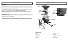
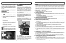
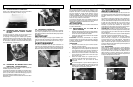
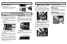
3-2. ATTACHING WHEEL ASSEMBLY TO
UNIT
1. Remove Top Cover Assembly by loosening the spring
loaded Top Cover Assemble Knobs. Figure 3-2A.
2. Lay motor assembly down on flat surface with plug
facing down.
3. Place a 2x4 under bottom of motor to obtain correct
angle to attach wheel kit.
4. Wheels should be toward floor (same as plug).
5. Align top of support tubes (2 holes) with 2 holes in
motor housing. Using hardware (flat washers of lock
washers, and 4 hex bolts attach support tubes to
motor housing & tighten.
6.
Stand unit of and install the Top Cover Assembly by
tightening the 3 spring loaded Top Cover Assembly
Knobs.
WARNING
Use caution when tightening set screws to avoid contact
with sharp cutting blades.
15.
The operation of any tool can result in foreign
objects being thrown into your eyes, which can
result in severe eye damage. Before operating power
tool, alw
ays wear safety goggles or safety glasses with
side shields and a full face shield when needed.We rec-
ommend wide Vision Safety Mask for use over eye-
glasses or standard safety glasses with side shields.
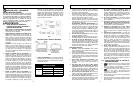
2-3. EXPLANATION OF NOTE, WARNING,
AND WARRANTY SYMBOL
1. A NOTE is used to convey additional information, or
highlight a particular explanation, or to expand a
instruction.
2. A WARNING identifies a procedure which, if not
undertaken or if improperly done, can result in a seri-
ous personal injury or damage to the unit and/or both.
3. (WARRANTY SYMBOL) serves notice that
unless instructions or procedures are followed,
any damage will void the warranty and all repairs will
be at owner's expense. Service other than user main-
tenance should be performed by a McCulloch
Authorized Service Center. Damage or conditions
caused by improper maintenance practices which ren-
der this product inoperable will void the manufactur-
er's warranty.
4.
FOR WARRANTY OR SERVICE contact the nearest
McCulloch Authorized Service Center.
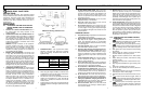
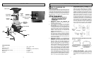
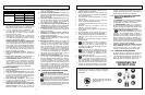
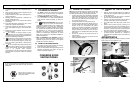
2-4. INTERNATIONAL SYMBOLS
1. Never place hands into Top Hopper, Side Chute or
Discharge Chute as ser
ious injury will occur (Figure
2-1).
2. Use of these personal safety items is highly recom-
mended to reduce the risk of accidental injury (Figure
2-2).
SAVE THESE
INSTRUCTIONS
6 7
2 - SAFETY PRECAUTIONS 3 - ASSEMBLY INSTRUCTIONS
3-1A
Axle
3-2A
Top Cover
Assembly
Top Cover
Assembly
Knobs
Use of these personal safety items is
highly recommended to reduce the risk
of accidental injur
y
.
Never place hands into Top Hopper,
Side Chute or Discharge Chute as
serious injury will occur.
2-1
2-2
Flat Washer
and Split Pin
3-1B
T
ube
Insert
Axle
Suppor
t
Tube
Allen hex screw,
small flat washer
and loc
k w
asher
3-2B
Chute
Screws
V
-Blade
Flange
Shredder
Blades