


8
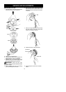
ASSEMBLY INFORMATION -- WEED
BLADE
WEED
BLADE
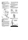
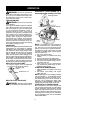
NOTE: Remove the trimmer head before
installingtheweedblade.Toremovethetrimmer
head, align hole in the dust cup with the hole in
the side ofthe gearbox by rotatingthe dust cup.
Insert a small screwdriver into aligned holes.
This will keep the shaft from turning while loos-
ening the trimmer head. Remove the trimmer
head by turning clockwise. Remove the screw-
driver .SeeINST ALLATION OFTHE CUTTING
HEAD for i llustrations. Besure tostore allparts
and instructions for future use. Never use the
trimmer head with the metal blade installed.
INSTALLATION O F THE METAL
BLADE
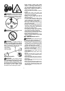
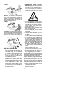
WARNING: W ear protective gloves
when handling or performing maintenance on
thebladeto avoidinjury. The b ladeis sharpand
can cut you even when it is not moving.
WARNING: Do not use any blades, or
fastening hardware other than t he washers and
nuts shown in the following illustrations. These
parts must be provided by McCulloch and
installed as shown below. Failure to use proper
parts can causetheblade toflyoff andseriously
hurt you or others.
NOTE: Thedust cupis locatedonthegearbox
shaft and not in the parts bag. All other fasten-
ers mentioned in the following assembly steps
are in the parts bag.
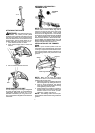
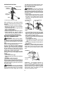
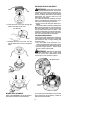
1. Install the blade and the retaining washer
over the threaded shaft.
2. Make sure the raised part of the retaining
washeris facingthegearboxand theraised
area fits into the hole in the center of the
blade.
3. Slide the blade and retaining washer onto
the shaft of the gearbox.
4. Place the cupped washer onto the shaft.
Make surethecupped sideof thewasher
is toward the blade.
5. Installthe bladenutby threading ontothe
shaft counterclockwise.
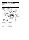
Shield
Blade
Retaining washer
Aligned holes
Cupped washer
Nut
Threaded
shaft
Wrench
Dust cup
Gearbox
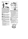
NOTE: Make sure all parts are in place as il-
lustrated, andthe bladeis sandwiched between
the dust cup and the retaining washer . There
should be no space between the blade and t he
dust cup or the retaining washer .
6. Align hole in dust cup with hole in side of
gearbox by rotating the blade.
7. Insert a small screwdriver into aligned
holes.This willkeeptheshaftfromturning
while tightening the blade nut.
8. Tighten blade nutfirmly with a wrench (pro-
vided) while ho lding screwdriver in position.
9. Remove the screwdriver.
10. Turn blade by hand. If the blade binds
against the shield, or appears to be un-
even, the blade is not centered, and you
must reinstall.
NOTE: To remove blade, insert screwdriver
into al ignedholes. Unthreadthenutandremove
parts. Be sureto storeparts andinstructions for
future use.
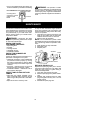
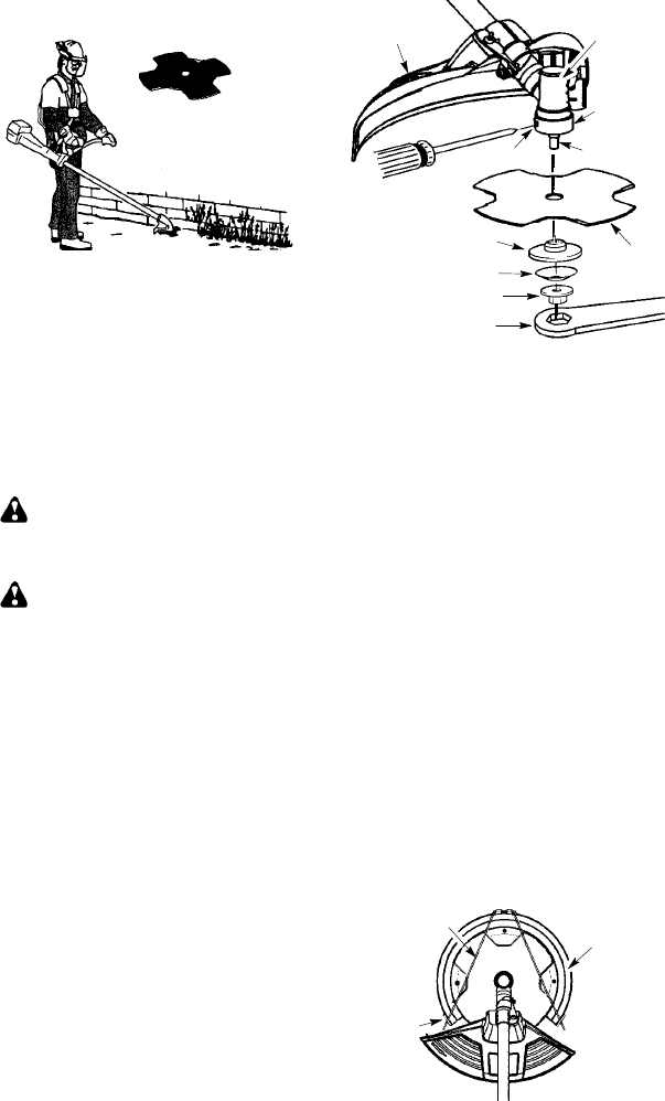
ATTACHING THE TRANSPORT
GUARD
NOTE:
Thetransport guardmust alw aysbe
attachedtothebladewhenthem achineisbe-
ing transported or in storage.
1. Remove ends of wire retainer from the
clips on the t ransport guard.
2. Lift wire retainer and position blade in
transport guard.
3. Place wire retainer over blade and insert
both ends ofwire re tainer back intoclips.
Wire retainer
Transport
guard
Clip