


7
76 cm
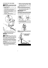
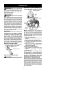
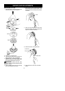
ATTACHING THE SHIELD
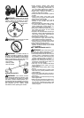
WARNING: The shieldmust beprop-
erly installed. The shield provides partial
protectionto theoperatorandothers fromthe
risk of thrown objects,and is equippedwith a
linelimiterblade whichcuts excessline tothe
proper length. The line limiter blade (on un-
derside of shield) is sharp and can cut you.
1. Insert bracket into slot on shield.
2. Pivot shield to align holes in shield and
bracket.
Slot
Shield
Bracket
3. Secure shield to bracket with bolt.
Bolt
CONFIGURING YOUR UNIT
You canconfigure yourunit usinga cuttinghead
for grass and light weeds, or a weed blade for
cutting grass, weeds, and brush up to 1 cm in
diameter. To assemble your unit, go to the sec-
tion for the desired configuration and follow the
instructions.
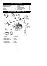
ASSEMBLY INFORMATION --
TRIMMER HEAD
TRIMMER
HEAD
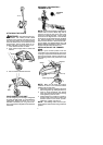
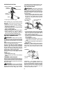
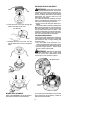
NOTE:Remove t heblade before a ttachingthe
trimmer h ead. To re move blade, align hole in
the dust cup with the hole in the side of the
gearbox by rotating the blade. Insert a small
screwdriver into alignedholes. Thi s will keep
the shaft from turning while loosening the blade
nut. Remove blade nut by turning clockwise.
Remove the screwdriver . Remove both wash-
ers and blade. See INSTALLA TION OF THE
METALBLADEforillustratio ns. Besuretostore
all parts and instructions for future use.
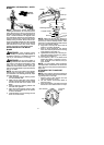
INSTALLATION OF THE TRIMMER
HEAD
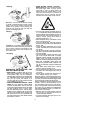
NOTE:
If your unit has a plastic cover over
thethreadsonthethreadedshaft,removethe
coveringtoexposethethreads.Beforeinstal-
lingthetrimmerhead,makesurethedustcup
and retaining washer are positioned on the
gearbox.
Retaining washer
Dust cup
Gearbox
Aligned holes
Shield
NOTE: Make sure all parts are properly
installed as shown in the illustration before
installing the trimmer head.
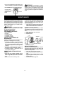
1. Align h olein t hedust cupwith t heholeinthe
side ofthegearbox by rotatingthe dust cup.
2. Insert a small screwdriver into aligned
holes.This willkeeptheshaftfromturning
while tightening trimmer head.
3. Whileholding the screwdriver inposition,
thread trimmer head onto the shaft in t he
direction shown on the decal (counter-
clockwise). Tighten until secure.
NOTE: Th e retaining washer must be posi-
tioned with the raised section facing toward the
gearbox.