27
TROUBLE-
SHOOTING
Note:
See engine owner’s manual for engine troubleshooting.
WARNING ICON G 001
WARNING
Only a qualified electrical service person should
service and repair generator. Use only factory
approved replacement parts.
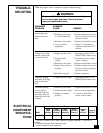
POSSIBLE
CAUSE
1. Defective capacitor
2. Winding short circuit
or loose connections
3. Defective rotor diode
4. Loss of residual
magnetism
1. Engine speed too low
2. Clogged spark
arrester
3. Defective rotor diode
4. Partial short circuit in
winding
5. Defective capacitor
1. Engine speed too high
1. Defective rotor diode
2. Electrical load too high
3. Engine not running
properly
OBSERVED
PROBLEM
No voltage when
starting generator
with no electrical
load
Voltage is less than
normal voltage with
no electrical load
Voltmeter reading
more than 10% high
with no electrical
load
Voltmeter reading
correct with no
electrical load, but
more than 10% low
when electrical load
is added
REMEDY
1. Replace capacitor
2. Check resistance of coils (see
Electrical Component Speci-
fications, below)
3. Replace both diodes on rotor
4. Apply 12-volt battery to
capacitor terminals for 2-3
seconds
1. Set engine speed to 3720
RPM (62 Hz) with no load
2. Clean arrester. See engine
owner’s manual
3. Replace both diodes on rotor
4. Check resistance of coils (see
Electrical Component Speci-
fications, below)
5. Replace capacitor
1. Set engine speed to 3720
RPM (62 Hz) with no load
1. Replace both diodes on rotor
2. Do not overload generator
3. Contact an authorized
engine service center
Resistance in Ohms
Stator Stator Rotor Rotor Capacitor,
Main Auxiliary Primary Secondary MFD Diodes (2)
Model Winding * Winding
∆
Winding † Winding † 450 Volt 800 Volt
MGY5000 0.54 1.38 0.61 2.29 50 70 Amp
ELECTRICAL
COMPONENT
SPECIFICA-
TIONS
* Connect T2 (green) and T3 (black). Measure resistance between T1 (red) and T4
(yellow).
∆ Resistance between brown and white leads.
† Remove diodes to check resistance.


