


P 2/ 8
Repair
It is not required to lubricate, because the product has no gear mechanism to be lubricated.
[3] DISASSEMBLY/ASSEMBLY
[3] -1. Switch
CAUTION: Repair the machine in accordance with “Instruction manual” or “Safety instructions”.
[1] NECESSARY REPAIRING TOOLS
[2] LUBRICATION
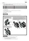
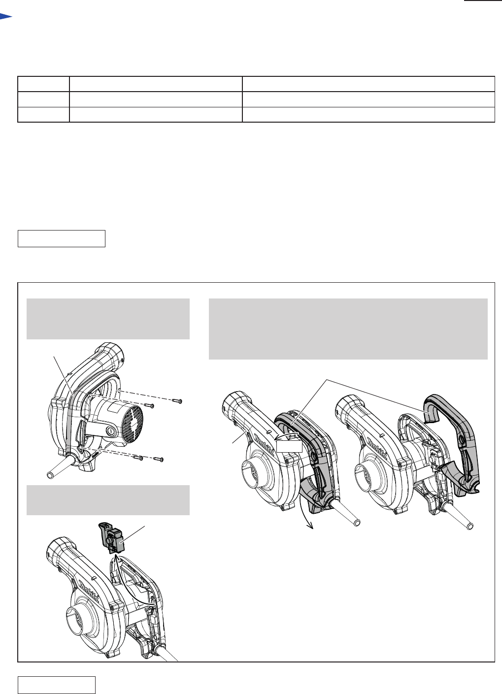
Fig. 1
DISASSEMBLING
ASSEMBLING
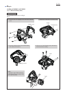
1. Switch can be disassembled without separating Fan housing complete section. See Fig. 1.
Code No. Description Use for
1R370 connecting Ring terminals to Brush holderRing Terminal Setting Jig
1R063 assembling Field to Motor housing completeGuide Bar for fitting Field
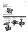
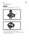
Assemble Switch by reversing the disassembly procedure. Refer to Fig. 1.
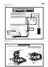
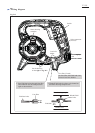
Note: When mounting Handle cover, be careful of the following.
• Switch and Lead wire are not pinched with Handle cover.
Refer to Fig. D-2 and Fig. D-3.
• There are no gaps between Handle cover and Fan housing complete.
No.1
No.2
Handle cover
Switch
Fan housing
complete
Handle cover
1. Remove four 4x18 Tapping screws
that secure Handle cover to Motor
housing.
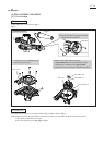
4. Remove Switch from Handle section
of Motor housing complete.
2. Separate Handle cover, pulling toward Fan housing complete side
(pulling toward the direction designated with arrow No.1.)
3. Disassemble Handle cover by broadening Handle cover (pulling
its ends toward the direction designated with arrow No. 2).
Now, Handle cover is removed.